- Why Sketch Constraints Matter More Than You Think
- The Three States of a SolidWorks Sketch
- All Constraint Types Explained
- How to Check and Diagnose Under-Defined Sketches
- Why Under-Defined Sketches Cause Real Problems
- Best Practices from Production Experience
- Practical Example: A Fully Defined Bolt Circle Sketch
- Common Mistakes and How to Avoid Them
- Key Takeaways
Why Sketch Constraints Matter More Than You Think
Every SolidWorks feature you build sits on top of a sketch. If that sketch is under-defined, your model is unpredictable. Dimensions change for no obvious reason, features fail during rebuilds, and parametric design intent goes out the window.
I have seen experienced engineers spend hours debugging a broken model only to trace the problem back to a single unconstrained sketch point from two years earlier. The fix takes thirty seconds — once you know where to look.
This guide covers every constraint type, explains why fully defined sketches matter in production environments, and gives you practical habits to apply immediately.
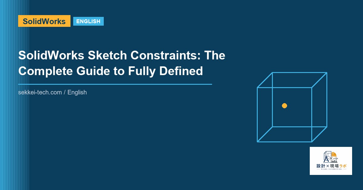
The Three States of a SolidWorks Sketch
SolidWorks uses color coding to tell you the state of every sketch entity:
- Blue = Under-defined. The entity has at least one degree of freedom remaining. It can move, rotate, or scale.
- Black = Fully defined. Every degree of freedom is constrained. This is the target state.
- Red = Over-defined or conflicting. Too many constraints are applied. SolidWorks cannot solve the sketch.
Check the status bar at the bottom of the screen. It explicitly says “Under Defined,” “Fully Defined,” or “Over Defined.” Never leave a sketch under-defined unless you have a deliberate reason — for instance, a sketch used as a path where one end remains intentionally free.
All Constraint Types Explained
Coincident
Forces two points, a point and a line, or a point and an arc endpoint to share the same location. This is the most frequently used constraint. Use it to connect endpoints of separate lines and close a sketch profile.
Shortcut: when you draw a line and snap to an existing point, SolidWorks adds a Coincident constraint automatically. If the yellow snap indicator does not appear, the constraint was not added. Zoom in and verify.
Parallel
Makes two lines run in the same direction. Essential for slot geometry, rectangular pockets, and any feature where walls must stay aligned regardless of dimension changes.
Parallel does not constrain position — only direction. You still need dimensions or other constraints to fix the distance between parallel lines.
Perpendicular
Forces a 90-degree angle between two lines. Combined with Parallel, these two constraints handle the majority of prismatic geometry. Use Perpendicular instead of a 90° angle dimension — it is geometrically exact and does not add unnecessary dimension entities.
Equal
Makes two or more entities the same size. Two lines become the same length. Two circles or arcs become the same radius. This is far better than typing the same dimension value twice. When you change one dimension, the equal entity updates automatically.
Equal is the foundation of symmetric geometry — use it with construction lines to create mirrored features that always stay balanced.
Symmetric
Mirrors two entities about a centerline. Select the centerline first, then the two entities. Symmetric is more powerful than Equal for mirrored geometry because it constrains both the size and the relative position about the mirror axis.
Common mistake: forgetting to constrain the centerline itself. If the centerline is free, the entire symmetric relationship drifts.
Midpoint
Places a point at the exact center of a line. Useful for centering geometry on an edge or aligning a hole to the midpoint of a slot. This constraint removes one degree of freedom — the point can still move along the line direction unless additional constraints are added.
Tangent
Connects an arc or circle to a line or another arc with zero angular discontinuity at the contact point. SolidWorks adds Tangent automatically when you draw a tangent arc, but verify it whenever arcs are close together. Missing tangency creates a visual kink and causes problems in downstream operations like shelling and offset surfaces.
Collinear
Places two or more lines on the same infinite line. Different from Parallel — collinear lines share the same geometric path, not just the same direction. Use it when you split a line into segments that must stay aligned end-to-end.
Concentric
Forces two circles, arcs, or circular edges to share the same center point. Effectively the same as adding a Coincident constraint between the two center points, but visually clearer and less prone to accidental deletion.
Horizontal and Vertical
Locks a line to run exactly horizontal or vertical relative to the sketch plane. Also applies to points — a Horizontal constraint between two points forces them to the same Y coordinate. These two constraints are automatically applied when you draw near-horizontal or near-vertical lines, which is usually correct behavior but can cause surprises on intentionally angled geometry.
Fix
Locks an entity’s position in space absolutely. This overrides all other constraints and dimensions. Use Fix sparingly — it makes the sketch rigid but breaks parametric intent. The one legitimate use case is fixing a reference entity that derives from an imported or legacy model.
How to Check and Diagnose Under-Defined Sketches
Open the sketch and drag individual entities. If something moves, it is under-defined. Click it and look at the Properties panel — it shows which constraints are applied and which degrees of freedom remain.
The most reliable diagnostic tool is Tools > Sketch Tools > Check Sketch for Feature. It reports open contours, zero-length entities, and self-intersections that prevent features from being created.
For complex sketches, use Display/Delete Relations (right-click menu). You can filter by “Dangling,” “Over Defined,” or “Under Defined” to isolate problem entities quickly.
Why Under-Defined Sketches Cause Real Problems
Consider a mounting bracket with a slot sketch. If the slot centerline has a free degree of freedom, the slot position can change every time SolidWorks rebuilds the model — for example, after you edit a parent feature. The slot shifts, the holes no longer align with the mating part, and the drawing dimensions become wrong.
In a PDM-controlled environment, that silent shift can propagate through an assembly without triggering a rebuild warning. Downstream drawings go out of date. Parts get manufactured incorrectly. I have seen this happen in production.
Fully defined sketches eliminate this class of failure entirely.
Best Practices from Production Experience
Start from the origin
Always constrain the first entity in every sketch to the sketch origin or an existing model edge. A floating profile that is not anchored to anything is always under-defined, even if every internal relationship is fully constrained.
Use a Coincident or Midpoint constraint to pin a strategic point to the origin. This anchors the entire sketch.
Use geometric constraints before dimensions
Add Parallel, Perpendicular, Equal, and Tangent constraints first. Then add dimensions. This approach uses fewer dimensions, makes the sketch easier to read, and makes dimension changes propagate more predictably.
A common beginner mistake is to dimension everything numerically and skip geometric constraints. The sketch works, but it is fragile — change one dimension and the geometry breaks because the constraint structure cannot handle it.
Avoid redundant dimensions
If a line is already defined as Horizontal, you do not need to add a 0-degree angle dimension. SolidWorks will accept it but mark the sketch over-defined. Over-defined sketches are equally dangerous — they make the solver choose arbitrarily which constraint to honor when they conflict.
Use construction geometry for references
Convert non-essential lines to construction geometry (toggle in Properties or press Q). Construction lines participate in constraints but do not form the feature boundary. This keeps the sketch profile clean and makes it obvious which geometry drives the feature.
Verify before closing
Before clicking the green checkmark to exit sketch mode, confirm the status bar reads “Fully Defined.” This takes two seconds and prevents hours of debugging later.
Practical Example: A Fully Defined Bolt Circle Sketch
Scenario: four M8 bolt holes on a 60 mm bolt circle, centered on the part origin, holes equally spaced at 90 degrees.
- Draw a centerline construction circle. Add a dimension: diameter 60 mm. Add Concentric to the origin.
- Draw one circle for the first hole. Add Coincident between the circle center and the construction circle. Add a dimension: diameter 8.5 mm (clearance for M8).
- Add a Vertical constraint between the first hole center and the origin (positions the first hole at 12 o’clock).
- Use Circular Pattern in sketch (Tools > Sketch Tools > Circular Sketch Pattern): 4 instances, 90 degrees spacing, centered on origin.
- Add Equal constraints between all four circles.
Status bar result: Fully Defined. The bolt circle will always be centered, always symmetric, always 60 mm diameter, regardless of how upstream geometry changes.
Common Mistakes and How to Avoid Them
| Mistake | Consequence | Fix |
|---|---|---|
| Not anchoring sketch to origin | Entire sketch drifts | Add Coincident/Midpoint to origin |
| Dimensioning instead of using Equal | Two values must be manually kept in sync | Replace duplicate dimensions with Equal constraint |
| Forgetting Tangent on arcs | Visual kink, shell failures downstream | Check arc endpoints with Display Relations |
| Using Fix on operational geometry | Breaks parametric updates | Reserve Fix for imported reference geometry only |
| Leaving dangling relations after geometry edits | Unpredictable rebuild behavior | Delete or reattach dangling relations immediately |
Key Takeaways
- Every sketch should be fully defined (black) before you exit sketch mode. Blue means trouble waiting to happen.
- Use geometric constraints (Parallel, Perpendicular, Equal, Tangent) before adding dimensions — fewer dimensions, more robust behavior.
- Always anchor the sketch to the origin or existing model geometry. A floating fully-constrained profile is still under-defined.
- Use Display/Delete Relations and Check Sketch for Feature to diagnose problems fast.
- In a team environment, under-defined sketches are a time bomb. Make fully defined sketches a non-negotiable standard.


コメント