
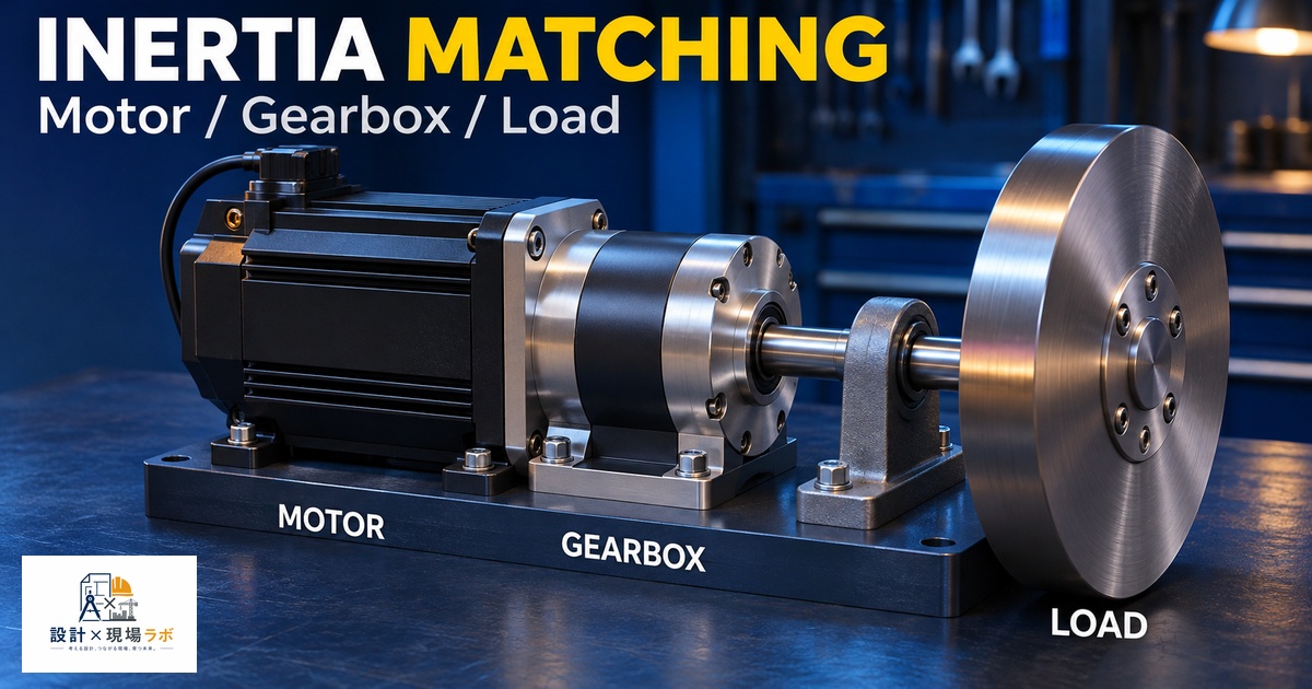
There’s a specific kind of frustration I’ve watched play out on more than one program: the mechanical design looks complete, the motor is sized with plenty of torque margin, the gearbox ratio hits the required output speed exactly, and then commissioning starts and the servo axis simply will not tune cleanly. It oscillates, overshoots, or hunts around the target position no matter how the gains are adjusted. Nine times out of ten in my experience, the root cause traces back to reflected inertia — specifically, a mismatch between the inertia the motor sees at its shaft and the inertia of the load it’s trying to control. This is a concept that gets a passing mention in most mechanical engineering curricula and then routinely gets under-weighted in real project schedules, right up until it causes a problem that’s expensive to fix late.
What Reflected Inertia Actually Means
Every rotating or linear load connected to a motor has its own inertia, but the motor doesn’t see that inertia directly unless it’s coupled 1:1. Any gear reduction between the motor and the load scales the inertia the motor actually experiences by the square of the reduction ratio. A 5:1 gearbox reduces the reflected load inertia by a factor of 25, and a 10:1 gearbox reduces it by a factor of 100. This squared relationship is the single most important thing to internalize about reflected inertia, because it means small changes in ratio produce dramatic changes in how the load feels to the motor and its control loop.
I explain this to junior engineers using a simple example: imagine trying to precisely control the rotation of a heavy flywheel by hand, directly on its shaft, versus through a long lever arm with significant mechanical advantage. The lever arm doesn’t change the flywheel’s actual inertia, but it changes how much effort and how much error-correcting force you can apply relative to how the flywheel responds. A servo’s ability to accelerate, decelerate, and hold position precisely depends on the torque it can command relative to the total inertia it’s driving — motor rotor inertia plus reflected load inertia — and that relationship is exactly what the gear ratio is manipulating.
The Inertia Ratio Rule of Thumb and Where It Comes From
The commonly cited guideline is to keep the ratio of reflected load inertia to motor rotor inertia somewhere between 1:1 and 10:1, with many drive manufacturers recommending staying under 5:1 for the best achievable dynamic performance and tuning stability. This isn’t an arbitrary number — it comes from how a servo control loop’s stability and bandwidth are affected by the total inertia it’s trying to control relative to the inertia it was effectively designed and tuned around, which is the motor’s own rotor inertia as the baseline reference.
When reflected inertia is low relative to motor inertia, the system behaves predictably and the drive’s control loop dominates the dynamics, giving clean, well-damped response. As reflected inertia climbs relative to motor inertia, the load starts to dominate the mechanical dynamics instead, and any compliance, backlash, or resonance in the coupling and transmission path becomes much harder for the control loop to manage. I’ve seen drives struggle to achieve stable gains at inertia ratios above 15:1 or 20:1 even on mechanically stiff systems, and the problem gets meaningfully worse once you introduce any real-world backlash or belt compliance into the drivetrain.
How Gearbox Ratio Affects Reflected Inertia
Because reflected inertia scales with the square of the inverse gear ratio, gearbox selection is one of the most powerful levers available for fixing an inertia mismatch, often more powerful than simply choosing a bigger motor. On the conveyor indexing project I mentioned in a related piece I wrote about gearbox selection, the initial 5:1 ratio reflected the load inertia at nearly 8:1 relative to the motor, well outside comfortable tuning range. Moving to a 10:1 ratio reduced reflected inertia by a factor of four relative to the 5:1 case, bringing the effective ratio down to roughly 2:1, and the tuning problem that had been unsolvable at the lower ratio disappeared almost as soon as the new gearbox was installed.
It’s worth being clear that increasing ratio isn’t a free lunch. Higher ratios generally mean higher gearbox cost, particularly for precision units, and can introduce efficiency losses and additional backlash depending on the gearbox type and number of stages, an issue I’ve written about separately when it comes to multi-stage planetary units. There’s also a practical ceiling: if the mechanical design already needs a specific output speed and torque, ratio changes have to be reconciled against those requirements too, sometimes requiring a different motor speed or an intermediate pulley stage to recover the target output speed, as we ended up doing on that conveyor project.
Consequences of Inertia Mismatch
The most visible symptom of a poor inertia ratio is difficulty tuning — the axis either oscillates when gains are pushed high enough for acceptable response time, or settles too slowly when gains are backed off enough to be stable. But there are subtler consequences too. Overshoot on rapid moves becomes harder to eliminate, which matters enormously on applications with tight positioning windows, like pick-and-place mechanisms or precision indexing stations. I worked on an assembly station where an axis with a marginal inertia ratio, right around 12:1, could be tuned to hit position within tolerance most of the time, but produced an intermittent overshoot on perhaps one cycle in a few hundred that was traced directly to the inertia mismatch amplifying a small resonance in the coupling.
Excessive mechanical stress is another consequence that’s easy to overlook. A high inertia ratio forces the control loop to work harder to achieve a given settling time, which means higher peak torque commands and correspondingly higher stress on the coupling, gearbox, and any belt or chain in the drivetrain. On that same assembly station, we eventually found premature wear on a flexible coupling that we traced back to the aggressive torque transients the drive was commanding to compensate for the inertia mismatch, essentially fighting a mechanical problem with control effort that the hardware wasn’t really designed to absorb continuously.
Calculating Inertia Ratio in Practice
The calculation itself isn’t complicated, but it requires pulling together numbers from several sources that don’t always live in the same document. You need the load inertia, calculated or estimated from the mass and geometry of everything the motor actually moves — not just the obvious payload, but couplings, pulleys, and any other rotating or reciprocating mass in the drivetrain. You need the gearbox ratio and, critically, the gearbox’s own reflected inertia contribution, which vendors do publish but which gets forgotten more often than it should, especially for multi-stage planetary units where the intermediate stages add non-trivial inertia of their own. And you need the motor’s rotor inertia, which is a straightforward datasheet number.
| Term | Where it comes from | Common oversight |
|---|---|---|
| Load inertia | Mass properties of driven components | Forgetting couplings and pulleys |
| Gearbox reflected inertia | Vendor datasheet | Often ignored entirely, especially on multi-stage units |
| Gear ratio squared factor | Basic reflection formula | Sign or ratio direction errors in spreadsheets |
| Motor rotor inertia | Motor datasheet | Confusing rotor inertia with total system inertia |
I keep a simple spreadsheet template for this calculation that I reuse across projects, specifically because I’ve seen enough one-off calculations done in a hurry that missed the gearbox’s own inertia contribution, which can be a meaningful fraction of the total on lower-ratio, larger-frame gearboxes even though it’s easy to assume the gearbox is inertia-neutral.
When to Break the Rule
The 10:1 guideline is useful as a default, but I don’t treat it as an absolute constraint, because the right answer depends on how aggressively the application actually needs to move and how forgiving the process is of settling time. On a slow-moving axis with generous positioning time and no tight overshoot requirement, I’ve accepted inertia ratios above 15:1 without issue, because the control loop simply didn’t need to be pushed hard enough for the mismatch to matter in practice. Conversely, on a high-speed pick-and-place axis with aggressive move-and-settle requirements, I’ve targeted ratios closer to 3:1 or better, even though it meant a more expensive gearbox, because the application’s dynamic requirements left no margin for the tuning compromises a higher ratio would have forced.
The honest answer is that the rule of thumb is a starting point for a conversation with the drive vendor and the motion control engineer, not a pass/fail gate to check once and move on from. Some modern servo drives have sophisticated enough tuning algorithms, including notch filters and adaptive tuning, to handle higher inertia ratios than the traditional guideline suggests, and I’ve seen that flexibility used deliberately to avoid an expensive gearbox upgrade on a program where budget pressure was real and the application’s dynamic requirements turned out to be more forgiving than the initial rule-of-thumb check suggested.
Real Project Examples
Looking back across a few programs where inertia ratio was the actual root cause of a schedule problem, the pattern is remarkably consistent: mechanical design and ratio selection happen early, often before a specific servo drive and its tuning characteristics are even finalized, and the inertia check either doesn’t happen at all or happens too late to change the gearbox without cost and schedule impact. The fix, every time I’ve seen it, is cultural rather than technical — building the reflected inertia calculation into the same early design review where torque and speed requirements get checked, rather than treating it as a commissioning-phase problem to solve after the hardware is already built. It’s a five-minute calculation that, done at the wrong stage of a project, becomes a multi-week fire drill instead.
Reference
Gear design has enough edge cases that a dedicated reference pays for itself the first time a tooth geometry question comes up.
Dudley’s Handbook of Practical Gear Design and Manufacture
As an Amazon Associate I earn from qualifying purchases.


コメント