
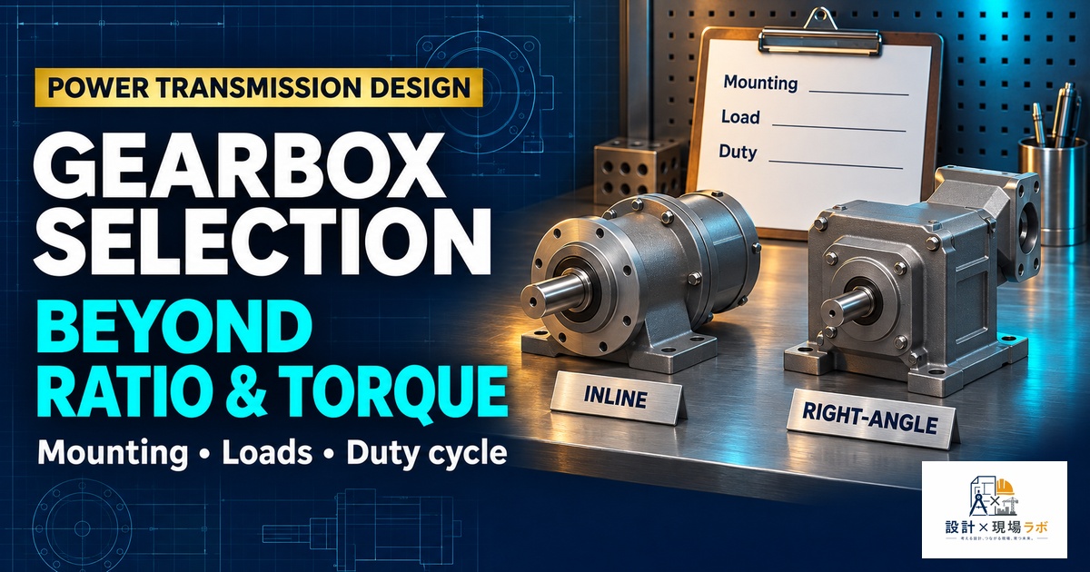
Selecting a gearbox looks like a simple catalog exercise until you’ve been burned by getting it wrong on an actual machine. I’ve spent a good chunk of my career as a contract mechanical designer embedded inside large manufacturers, and gearbox selection is one of those tasks that junior engineers often treat as a lookup problem — find the ratio that gets you the output speed you want, pick a frame size that fits the torque, done. In reality, ratio and torque are just the entry point. Backlash, mounting configuration, overhung load, thermal derating, and how the gearbox physically integrates with the rest of the machine all matter just as much, and I’ve seen programs slip by weeks because one of those secondary factors got treated as an afterthought.
- Understanding Reduction Ratio and Its Trade-offs
- Torque Rating, Service Factor, and Overhung Load
- Backlash and Positioning Accuracy
- Gearbox Types: Planetary, Worm, Helical, and Cycloidal
- Mounting Configurations: Inline, Right-Angle, Foot vs Flange
- Efficiency and Thermal Considerations
- Selection Mistakes I’ve Seen Repeated
- Reference
Understanding Reduction Ratio and Its Trade-offs
The reduction ratio is usually the first number everyone locks onto, because it directly sets the relationship between motor speed and output speed. But the ratio decision is never just about matching a target output RPM — it’s also about where you want your torque multiplication and inertia reflection to land. A higher ratio gives you more torque multiplication and, just as importantly, reduces the reflected inertia the motor sees, which makes tuning a servo loop considerably easier. I worked on a conveyor indexing application where the initial mechanical concept called for a 5:1 ratio because that hit the target speed exactly, but the reflected inertia at that ratio was nearly eight times the motor’s rotor inertia, and the servo tuning team could not get acceptable settling behavior no matter what they did to the gains.
We revisited the ratio, moved to 10:1, and added a small pulley stage to recover the target output speed. Reflected inertia dropped to a manageable ratio, and the servo tuning problem disappeared almost immediately. The lesson wasn’t that higher ratios are always better — there are efficiency and cost penalties as ratio climbs, particularly with multi-stage planetary units — but that ratio selection has to be made jointly with the motion control engineer, not handed off as a pure mechanical speed-matching exercise.
Torque Rating, Service Factor, and Overhung Load
Every gearbox has a continuous torque rating and usually a separate peak or intermittent rating, and mixing these up is a classic mistake. I reviewed a design once where the selected gearbox’s peak torque rating happened to match the application’s peak load almost exactly, which looked fine until you noticed the peak load occurred multiple times per minute during normal operation, not as a rare fault condition. That’s a continuous-duty problem being solved with a peak-duty number, and the gearbox failed prematurely in early production units through accelerated wear on the output bearings.
Service factor exists precisely to build margin into a selection for real-world duty cycles, shock loading, and starts-per-hour, and I’ve learned to be conservative with it rather than trusting a single nominal torque calculation. Overhung load is the other factor that gets missed constantly, especially when a pulley, sprocket, or coupling is mounted directly on the gearbox output shaft with some radial offset from the bearing. The overhung load rating in the catalog is usually specified at a particular distance from the shaft shoulder, and if your actual load application point sits further out than that reference distance, the effective allowable load drops significantly. On a belt-driven application I designed, we initially mounted the pulley further out on the shaft than the vendor’s reference point to clear a frame member, and had to go back and recalculate allowable overhung load at the actual distance, which pushed us to a larger frame size than the torque number alone would have suggested.
Backlash and Positioning Accuracy
Backlash matters enormously for any application involving position control, reversing loads, or precise indexing, and matters much less for something like a simple conveyor drive running in one direction under steady load. Standard helical or worm gearboxes can have several arc-minutes of backlash, which sounds tiny until you translate it into linear position error at the end of a long lever arm or a large-diameter output. I worked on a rotary indexing table where a standard planetary gearbox with roughly 8 arc-minutes of backlash translated into position repeatability that was three times worse than the process spec required, because the table diameter amplified that angular error into unacceptable linear error at the tooling location.
Switching to a precision planetary or a cycloidal reducer, both of which are available in low-backlash variants down to 1 arc-minute or better, solved the accuracy problem but came with a real cost premium that had to be justified against the process requirement. This is a case where I always push teams to define positioning accuracy requirements in linear terms at the point that actually matters, then convert back to allowable backlash, rather than picking a gearbox class first and hoping it works out.
Gearbox Types: Planetary, Worm, Helical, and Cycloidal
| Type | Strengths | Watch-outs |
|---|---|---|
| Planetary | High torque density, low backlash options, coaxial | Cost rises fast with precision grade |
| Worm | High single-stage ratio, self-locking, quiet | Lower efficiency, heat generation at high duty cycle |
| Helical (parallel or right-angle) | High efficiency, robust, good for continuous duty | Larger footprint for equivalent ratio |
| Cycloidal | Very low backlash, high shock tolerance | Higher cost, more complex to service |
Worm gearboxes deserve special mention because the self-locking property gets treated as a free safety feature more often than it should. I’ve seen designs rely on worm gearbox self-locking to hold a vertical load in place with the motor de-energized, which works under ideal conditions but is not something I’d certify as a safety function without a separate mechanical brake, because self-locking behavior can degrade with wear, lubrication condition, and vibration over the life of the machine. On an application with a genuine fall-hazard if the load dropped, we added a spring-applied brake on the motor regardless of the worm gearbox’s self-locking rating, purely because the consequence of being wrong was too high to accept on a gearbox characteristic that isn’t guaranteed over the full service life.
Mounting Configurations: Inline, Right-Angle, Foot vs Flange
Mounting configuration is often decided by the machine layout rather than by the gearbox itself, but it has real consequences for bearing loads and alignment sensitivity. Flange mounting, where the gearbox bolts directly to the driven machine with a close-coupled shaft connection, minimizes misalignment risk and saves space, but it also means any thermal expansion or frame deflection gets transmitted more directly between the two components. Foot mounting with a separate coupling gives more installation flexibility and tolerance for minor misalignment, at the cost of extra footprint and an additional component, the coupling, that has its own failure modes to consider.
Right-angle gearboxes solve a real layout problem when motor space is constrained, but I’ve found they introduce their own headache in that the bevel or worm gear stage inside them typically has lower efficiency and a different thermal profile than an equivalent inline unit, which matters if the application runs near continuous duty. On a packaging machine retrofit where space genuinely required a right-angle configuration, we had to add a small increase in motor sizing specifically to cover the efficiency loss through the right-angle stage, something that wasn’t obvious from the torque numbers alone until we dug into the vendor’s efficiency curve at our actual operating speed.
Efficiency and Thermal Considerations
Efficiency losses in a gearbox show up as heat, and at sustained high duty cycles that heat has to go somewhere. Worm gearboxes are the worst offenders here, sometimes running as low as 50 to 60 percent efficient at high ratios, compared to 90 percent or better for a well-designed helical or planetary unit. I worked on an application originally specified with a worm gearbox for its compact right-angle form factor and self-locking property, but once we ran the actual duty cycle numbers, the continuous heat generation exceeded the gearbox’s thermal rating for the ambient enclosure temperature it would operate in.
We ended up switching to a helical-bevel unit with a coupling-mounted brake to replace the lost self-locking function, which solved both the thermal problem and the safety concern from the earlier point about self-locking reliability. It’s a good example of how gearbox selection issues tend to compound — fixing one constraint properly often resolves a second one you hadn’t fully closed out yet.
Selection Mistakes I’ve Seen Repeated
Looking back across enough projects, the same handful of mistakes keep resurfacing. Selecting on nominal torque without checking service factor against actual duty cycle is probably the most common. Ignoring overhung load at the actual mounting distance rather than the catalog reference distance is a close second. Treating backlash as a spec sheet number rather than converting it into real positional error at the point that matters is a third. And finally, deciding ratio in isolation from the motion control team, without checking reflected inertia, is a mistake I’ve now seen enough times that I raise it explicitly in every servo-driven gearbox selection I’m involved in, regardless of how confident the initial mechanical sizing looks on paper.
Reference
Gear design has enough edge cases that a dedicated reference pays for itself the first time a tooth geometry question comes up.
Dudley’s Handbook of Practical Gear Design and Manufacture
As an Amazon Associate I earn from qualifying purchases.


コメント