
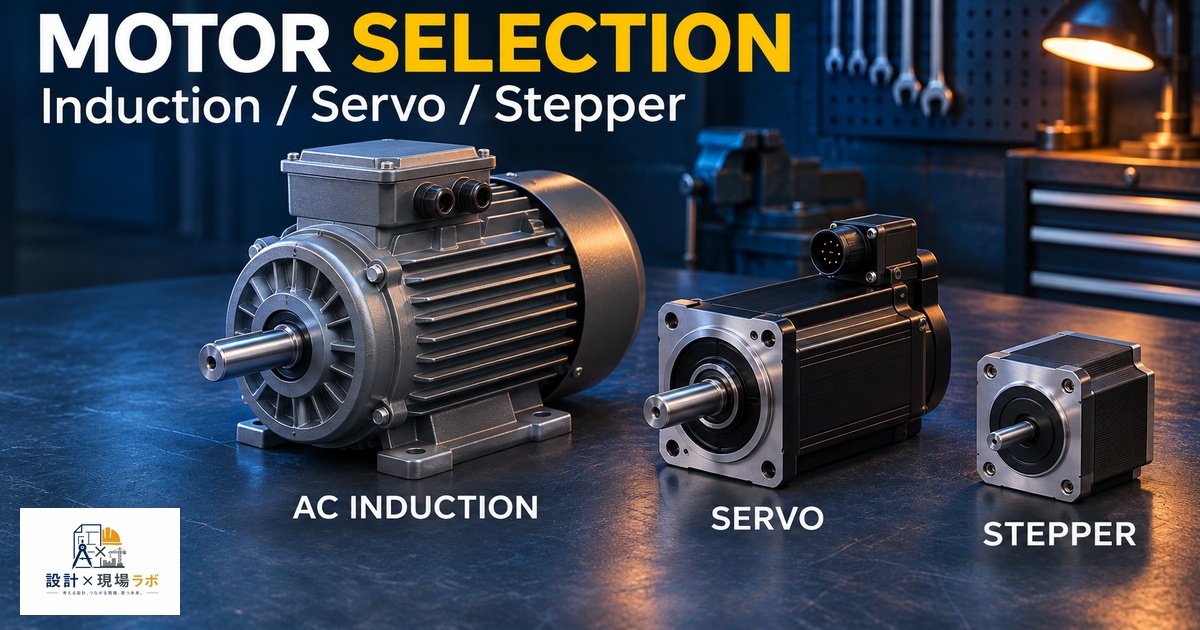
Motor selection is one of those decisions that gets made surprisingly early in a project, often before the mechanical concept is even fully locked down, and yet it constrains almost everything that follows — control architecture, cost, cabinet space, and how much tuning effort the commissioning team is going to be doing months later. Over twenty years of contract mechanical design work inside large manufacturing environments, I’ve specified all three of the major motor families discussed here on different programs, sometimes on the same machine for different axes, and I’ve watched teams default to whichever motor type they used last time rather than actually reasoning through the application. This is a rundown of how I actually think through the choice.
Basic Operating Principles
AC induction motors are the workhorses of general industrial equipment, and their appeal starts with simplicity: a rotating magnetic field in the stator induces current in the rotor, which creates torque, with no permanent magnets and no direct electrical connection to the rotor at all. That simplicity translates into ruggedness and low cost, and it’s why induction motors dominate applications like pumps, fans, and conveyor drives where precise position control isn’t the point.
Servo motors, typically permanent magnet synchronous types in modern industrial applications, use magnets embedded in or mounted on the rotor and rely on a drive that commutates the stator current based on rotor position feedback from an encoder or resolver. This closed-loop arrangement is what gives servos their defining characteristic: the drive always knows exactly where the rotor is and can correct for load disturbances in real time.
Steppers work differently again. They move in discrete angular increments by energizing stator windings in a sequence, and in their most common open-loop implementation, the controller assumes the rotor followed each commanded step without ever confirming it did. That assumption is both the stepper’s greatest strength, in terms of control simplicity and cost, and its most dangerous weakness, which I’ll come back to.
Torque-Speed Characteristics
The torque-speed curve is where these three motor types really start to diverge in ways that matter for selection. Induction motors deliver relatively flat torque across a moderate speed range near their rated speed but lose torque outside that band unless paired with a variable frequency drive that manages the volts-per-hertz curve carefully. Servos maintain strong torque from zero speed all the way to relatively high speeds, and can deliver peak torque several times their continuous rating for short bursts, which is exactly what you want for rapid acceleration and deceleration in motion-intensive applications.
Steppers have an almost inverse relationship — they produce their highest torque at zero and low speed, and torque falls off sharply as speed increases, sometimes dropping by more than half by the time you reach a few hundred RPM. I learned this the hard way early in my career on a small pick-and-place mechanism where the stepper was sized based on its holding torque rating, without adequately checking the torque available at the actual operating speed the motion profile required. The motor stalled intermittently during the fast traverse move, and the fix required either slowing the profile down or switching to a larger frame stepper with more torque margin at speed — we chose the latter because cycle time was a hard requirement on that program.
Control Complexity and Cost
Cost and control complexity roughly track each other across these three types, though not always predictably. A stepper with a basic open-loop driver is the cheapest system to implement, both in hardware and in the engineering time required to get it running, because there’s no tuning loop to close — you commission it largely by verifying the motion profile stays within the motor’s torque capability. Induction motors with a standard variable frequency drive sit in the middle; the drive itself is inexpensive and well understood, but achieving precise speed regulation, especially at low speed, requires either open-loop volts-per-hertz control, which has real limitations, or closed-loop vector control with an encoder, which starts to close the cost and complexity gap with a servo system.
Servos are the most expensive to implement both in hardware and in commissioning labor, because every axis needs to be tuned, and tuning a servo loop well, particularly on a mechanical system with real compliance and backlash, is a genuine skill that takes time to develop. On one machine I worked on with six servo axes, commissioning and tuning consumed nearly three weeks of the schedule, far more than the mechanical build itself, and that’s time a project plan has to account for honestly rather than treating servo tuning as an afterthought that happens automatically once the drive is powered up.
Precision and Feedback
This is really the crux of the decision for a lot of applications. Servos, with their closed-loop position feedback, deliver the highest precision and can detect and correct for a stall or missed step condition in real time, which makes them the right choice whenever position accuracy is critical or the load can vary unpredictably. Steppers, in their common open-loop form, have no such feedback — if the motor stalls due to an unexpected load spike, friction increase, or mechanical jam, the controller has no idea the position was lost, and the machine continues operating as if nothing happened, silently accumulating position error.
I dealt with exactly this failure mode on a labeling machine where a stepper-driven axis occasionally lost steps due to a sticky guide rail that developed friction variation as it wore. Because there was no feedback, the machine kept placing labels at an increasingly wrong position for dozens of cycles before an operator noticed the defect visually. We ultimately retrofitted closed-loop steppers, which add an encoder and a drive that can detect and correct for missed steps, as a middle-ground fix that avoided a full servo conversion while closing the actual gap that had caused the failure. Closed-loop stepper technology has matured a lot in recent years and is worth considering whenever cost pressure makes a full servo system hard to justify but the application genuinely needs the assurance of feedback.
Application Fit: How I Actually Choose
| Application characteristic | Typical fit | Why |
|---|---|---|
| Continuous rotation, no precise positioning, cost-sensitive | AC induction | Rugged, cheap, well understood |
| Fast, precise point-to-point motion, variable load | Servo | Closed-loop response, high dynamic performance |
| Low-cost indexing, light and predictable load | Open-loop stepper | Simple control, no tuning required |
| Indexing with load uncertainty or long travel | Closed-loop stepper | Adds fault detection without full servo cost |
| Continuous duty at varying speed, moderate precision | Induction with vector drive | Balance of cost and speed regulation |
I treat this table as a starting point rather than a final answer, because real applications almost always have a wrinkle that shifts the decision. On a filling machine I worked on, the nominal load was light and predictable, which pointed toward an open-loop stepper, but the process occasionally experienced a jam condition that absolutely had to be detected rather than silently ignored, given the downstream consequences of a missed fill. That single failure-mode requirement was enough to justify the extra cost of a closed-loop stepper over the cheaper open-loop option, even though the baseline torque and speed requirements alone wouldn’t have demanded it.
Sizing and Common Mistakes
Undersizing torque margin is the single most common mistake I see across all three motor types, but it manifests differently in each. On induction motors, undersizing shows up as excessive slip and overheating under sustained load. On servos, it shows up as the drive hitting its current limit during acceleration, which can cause following error faults during tuning that get misdiagnosed as a tuning problem when the real issue is inadequate torque headroom. On steppers, as I mentioned earlier, it shows up as silent stalling, which is the most dangerous of the three failure modes precisely because there’s often no fault indication at all.
The other recurring mistake is sizing purely to the continuous duty point without checking acceleration torque, especially for servos and steppers where rapid moves are the whole point of choosing that motor family in the first place. I always calculate peak torque required through the actual acceleration profile, including the reflected inertia of any gearbox and coupled load, before finalizing a motor frame size, rather than relying on a continuous torque number that only tells part of the story.
Maintenance and Reliability
Induction motors are generally the most maintenance-friendly of the three, with no brushes in modern squirrel-cage designs and few wear items beyond bearings, which is part of why they remain the default choice for equipment that just needs to run reliably for years with minimal attention. Servo motors, being more electronically complex with encoders and higher-performance bearings, tend to have more failure points, though modern industrial servo motors are still quite robust when properly sized and not run at their thermal limits continuously.
Steppers sit in an interesting spot: mechanically simple and reliable as a motor, but the open-loop control scheme means the reliability of the overall system depends heavily on the mechanical design staying within the torque margin assumed at commissioning, for the entire service life of the machine. I’ve seen stepper-driven axes that worked flawlessly for years suddenly develop stall problems after a bearing wore slightly or a lubricant degraded, precisely because the original torque margin was thin and had no feedback mechanism to flag the gradual degradation before it became a visible defect. That’s ultimately the deciding factor I come back to again and again: it’s not just about what torque and speed a motor needs today, but how much margin and feedback the application needs against how that mechanical system will behave years into its service life.


コメント