
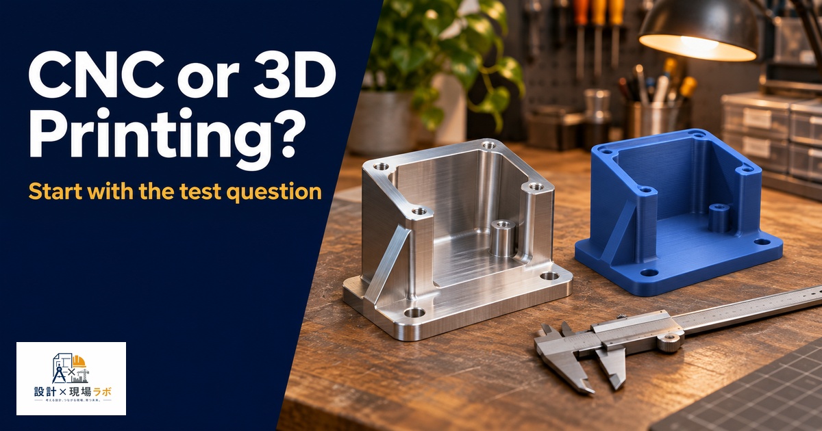
I have lost count of the number of design review meetings where someone asks “can we just print it” as though the answer is obvious, and I understand the impulse — additive manufacturing has gotten remarkably good over the last decade, and the marketing around it makes every prototyping decision sound like it should default to a printer. But after twenty years designing mechanical components as a contract engineer inside major manufacturers in Japan, I can tell you the real answer is almost always “it depends on what you’re trying to prove.” CNC machining and 3D printing solve different problems, and choosing wrong wastes not just money but, more importantly, time you cannot get back before a design freeze. This article is my honest breakdown of when I reach for each method, based on prototypes that worked, prototypes that misled us, and a few that cost us a full development cycle because we chose the fast option instead of the right one.
- What “Functional Prototype” Actually Needs to Prove
- Material Fidelity: Where 3D Printing Most Often Misleads You
- Where CNC Machining Earns Its Higher Cost and Longer Lead Time
- Speed and Iteration: Where Printing Wins Decisively
- A Decision Framework I Actually Use
- Combining Both Methods Instead of Choosing One
What “Functional Prototype” Actually Needs to Prove
The mistake I see most often is treating “functional prototype” as a single category when it actually spans a wide range of purposes. A prototype meant to verify that a cable routes correctly through a housing needs geometric accuracy and nothing else — material properties barely matter. A prototype meant to verify that a snap-fit latch survives 500 cycles needs material properties that closely match production plastic, because a printed part in a different polymer with different layer adhesion will give you a false pass or a false fail. A prototype meant to verify that a bracket survives a shock load in a drop test needs both geometry and material behavior close enough to production that the failure mode you observe is the failure mode you would actually see in the field.
On a conveyor guide rail project, I once approved a printed prototype for a load-bearing bracket without fully separating these purposes in my own head. The print looked right, assembled correctly, and even survived a static load test at the design load. But the bracket failed in the field within weeks because the actual duty cycle involved repeated impact loading from product drops onto the rail, and the FDM print’s layer lines created a stress concentration plane that behaved nothing like the injection-molded production part would. The prototype had proven geometry and proven static strength, but it had never been asked to prove fatigue behavior, and I had let the team treat “it passed the test we ran” as “it will work,” which are not the same claim.
Material Fidelity: Where 3D Printing Most Often Misleads You
The single biggest risk I have seen with 3D printed functional prototypes is engineers forgetting that print materials are not the same as production materials, even when the datasheet lists similar tensile strength numbers. FDM parts are anisotropic — strong along the print plane, weak between layers — in a way that injection-molded or machined parts simply are not. SLA and SLS materials behave more isotropically, but they still diverge from production nylon or polycarbonate in impact resistance, long-term UV stability, and creep behavior under sustained load.
I ran into this directly on a housing clip design where an SLS nylon prototype passed a hand-flex test that the design team used as an informal pass/fail gate before committing to injection tooling. The SLS material felt appropriately springy and returned to shape exactly like we expected production nylon to behave. When the actual injection-molded part came off first-shot tooling, it was noticeably stiffer and more brittle at the clip root because the glass-fiber loading in the production resin, added for dimensional stability elsewhere in the part, changed the flex behavior in a way the unfilled SLS prototype material never could have revealed. We caught it before it shipped, but only because a cautious quality engineer insisted on testing first-shot parts before sign-off rather than trusting the earlier prototype result. Since then, I treat any snap-fit or living-hinge feature as requiring either a machined prototype in the actual production resin (via a small block of stock material) or, when budget allows, a soft-tool first-shot sample — never a printed proxy — before I sign off on flex-critical geometry.
Where CNC Machining Earns Its Higher Cost and Longer Lead Time
CNC machining costs more per part and takes longer to turn around than most desktop or even industrial 3D printing, and I do not want to pretend otherwise — a five-axis machined aluminum bracket that might cost 40,000 yen and take four days can often be printed in PLA overnight for a fraction of the cost. But when the prototype needs to validate dimensional tolerances tighter than about ±0.1mm, or needs a true representative surface finish for a sealing interface, or needs to be metal because the application involves temperatures a polymer print cannot survive, CNC is not a luxury — it is the only method that answers the question being asked.
On a hydraulic manifold project, we needed to validate an O-ring groove geometry before committing to a casting pattern. The groove depth tolerance was ±0.05mm, and the surface finish requirement for the sealing face was specified at a roughness value no printed process could realistically hit without substantial post-machining anyway. We machined the prototype manifold from a billet of aluminum, and the leak test we ran on it was directly predictive of how the eventual cast-and-machined production part would perform, because the sealing surface itself was produced by the same process family — machining — that would finish the production casting. A printed prototype here would have told us nothing useful about seal performance; at best it would have told us the bolt pattern cleared the mating flange, which we could have verified with a simple 2D check fixture for a tenth of the cost.
Speed and Iteration: Where Printing Wins Decisively
I do not want this article to read as an argument against 3D printing, because on plenty of projects it has saved me weeks. When a design is still in the geometry-exploration phase — when the real question is “does this fit,” “does this clear that cable,” “does this feel right in a technician’s hand” — 3D printing is unambiguously the better tool, because you can iterate same-day. On an enclosure project with a tight cable entry, I went through eleven printed iterations of a strain-relief boss over about two weeks, something that would have been financially and logistically impossible with CNC machining at that pace. Each iteration cost us maybe 45 minutes of print time and a few hundred yen in filament, and by the time we locked the geometry, we had eliminated an entire category of assembly complaints before a single machined part existed.
The same logic applies to ergonomic and fit-check prototypes for anything a human interacts with directly. A control panel enclosure, a hand tool housing, a knob — these benefit enormously from rapid printed iteration because the feedback loop that matters is human judgment on shape and feel, not material performance under load. I have never once needed a machined prototype to answer “does this knob feel right to turn,” and I would consider it wasteful to reach for CNC for that kind of question.
A Decision Framework I Actually Use
| Question the prototype must answer | Preferred method | Why |
|---|---|---|
| Does the geometry fit and clear other parts | 3D printing | Fast, cheap, iteration speed matters more than fidelity |
| Does a snap-fit or living hinge survive repeated flex | Machined in production resin, or soft-tool sample | Print anisotropy misrepresents flex fatigue |
| Does a sealing surface hold pressure | CNC machining | Surface finish and tolerance directly affect seal performance |
| Does a bracket survive shock or fatigue loading | CNC in production-representative material | Layer lines create false failure modes in prints |
| Does an operator’s hand fit the grip comfortably | 3D printing | Human judgment matters more than material accuracy |
| Does a tight tolerance stack-up actually assemble | CNC machining | Print dimensional accuracy is usually ±0.2-0.3mm at best |
I keep something close to this table pinned near my desk, not because the categories are exhaustive, but because forcing myself to write down what question a prototype is supposed to answer, before I request it, has saved me from more than one embarrassing mismatch between test result and reality.
Combining Both Methods Instead of Choosing One
The most effective prototyping strategy I have used on complex assemblies is not “CNC or printing” but a deliberate sequence of both. On a pump housing project, we ran three loose-fit iterations of the full housing in SLA to validate the internal flow path geometry and impeller clearance, changing wall contours between each print based on a bench flow test. Once the internal geometry was locked, we moved to a single CNC-machined aluminum prototype specifically to validate the pressure-retaining wall thickness and to run an actual hydraulic pressure test to 1.5 times rated pressure, something the SLA prints were never intended to survive and were never asked to.
This staged approach cost more in total prototype spend than either method alone, but it was dramatically cheaper than machining every iteration during the geometry-exploration phase, and dramatically safer than pressure-testing a printed part and treating a print survival result as evidence about the metal design. The lesson that has stuck with me across two decades of this work is that the question “CNC or 3D printing” is the wrong question to start with. The right first question is “what specifically does this prototype need to prove,” and the manufacturing method falls out of that answer almost automatically once you are honest about it.


コメント