More than 80% of all mechanical failures in service are fatigue failures — and most of them occur at stress levels far below the material’s yield strength, which is why static stress calculations alone are never sufficient for parts subject to cyclic loading.
Fatigue is the progressive, localized structural damage that occurs when a material is subjected to repeated or fluctuating loads. A crack initiates at a stress concentration or surface defect, propagates with each load cycle, and ultimately causes sudden fracture. This guide covers the S-N curve approach, the endurance limit concept, Marin modification factors, and the modified Goodman diagram for mean stress correction — the essential toolkit for fatigue analysis in mechanical design.
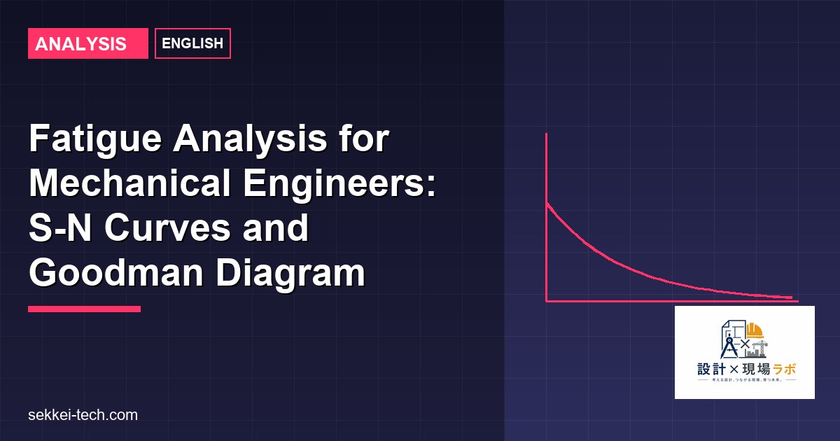
The S-N Curve (Wöhler Curve)
The S-N curve (stress vs. number of cycles to failure) is determined by testing polished, standard specimens under fully reversed bending (mean stress = 0, stress ratio R = −1). For steels, the S-N curve has a characteristic “knee” at approximately 10⁶ cycles, below which the endurance limit Se is the stress amplitude that can be sustained indefinitely (infinite life).
Key points on the steel S-N curve:
- At N = 10³ cycles: S ≈ 0.9 × Sut (near-static failure)
- At N = 10⁶ cycles: S ≈ Se (endurance limit)
- For N > 10⁶: stress remains at Se (infinite life for most steels)
The laboratory endurance limit for polished steel specimens is approximately:
Se ≈ 0.5 × Sut for Sut ≤ 1400 MPa
Se ≈ 700 MPa for Sut > 1400 MPa
Important: Non-ferrous metals and alloys (aluminum, copper, titanium) generally do not exhibit a true endurance limit — their S-N curves continue to decline with increasing cycles. For aluminum, a “fatigue strength” at 5×10⁸ cycles is commonly used instead of an endurance limit.
Marin Modification Factors
The laboratory endurance limit significantly overpredicts the fatigue strength of real machine parts. Joseph Marin proposed a set of multiplicative factors to correct the laboratory value to the actual component endurance limit S’e:
S’e = ka × kb × kc × kd × ke × Se
Surface finish factor ka = a × Sutb where a and b are empirical constants from Shigley’s:
| Surface Condition | a (MPa units) | b | ka at Sut=700MPa |
|---|---|---|---|
| Ground | 1.58 | −0.085 | 0.90 |
| Machined or cold-drawn | 4.51 | −0.265 | 0.72 |
| Hot-rolled | 57.7 | −0.718 | 0.52 |
| As-forged | 272 | −0.995 | 0.39 |
Size factor kb: For rotating round specimens in bending: kb = 1.24 × d-0.107 for 2.79 mm ≤ d ≤ 51 mm; kb = 1.51 × d-0.157 for 51 mm < d ≤ 254 mm. For non-rotating or non-circular sections, an equivalent diameter is calculated. kb ≈ 0.85 for d = 25–50 mm, ≈ 0.75 for d = 50–150 mm.
Load factor kc: kc = 1.0 for bending, 0.85 for axial loading, 0.59 for torsion. The lower value for torsion reflects that the endurance limit in shear is lower than in bending.
Temperature factor kd: kd = 1.0 for T < 450°C for steel. Above 450°C, both Sut and Se decrease with temperature. Use temperature-corrected Sut values. Below 0°C, most steels become more brittle — fatigue is actually less of a concern than brittle fracture at cryogenic temperatures.
Reliability factor ke: Fatigue data shows significant scatter; ke accounts for the statistical reliability of the endurance limit estimate:
| Reliability | ke |
|---|---|
| 50% (mean, no factor) | 1.000 |
| 90% | 0.897 |
| 95% | 0.868 |
| 99% | 0.814 |
| 99.9% | 0.753 |
Combined effect: for a machined steel shaft (ka = 0.72, kb = 0.85, kc = 1.0, kd = 1.0, ke = 0.814 for 99% reliability), S’e = 0.72 × 0.85 × 1.0 × 1.0 × 0.814 × Se = 0.498 × Se. For steel with Sut = 700 MPa: S’e = 0.498 × 350 = 174 MPa. This is only 25% of Sut — the Marin factors collectively cut the endurance limit in half compared to the laboratory specimen.
Stress Concentration in Fatigue
In fatigue calculations, the alternating stress amplitude must be multiplied by the fatigue stress concentration factor Kf to account for the stress-raising effect of notches, keyways, holes, and other geometric discontinuities:
Kf = 1 + q × (Kt − 1)
Where Kt = theoretical stress concentration factor (from stress concentration charts based on geometry), and q = notch sensitivity (0 to 1). Notch sensitivity q is higher for harder, stronger steels and lower for softer steels and cast iron. For high-strength steels (Sut > 1000 MPa), q approaches 1.0 and Kf ≈ Kt. For mild steel (Sut = 350–500 MPa), q ≈ 0.6–0.75.
The effective alternating stress: σa,eff = Kf × σa. Note that the mean stress is multiplied by Kfm ≤ Kf for static (mean) stress components — ductile materials can locally yield and redistribute mean stress, reducing its effective concentration. The convention in Shigley’s is to apply Kf to alternating stress and 1.0 to mean stress for ductile materials (conservative) or to use Kf for both.
Modified Goodman Criterion
Real parts rarely experience pure fully reversed loading. They typically have a non-zero mean stress (σm) in addition to the alternating stress (σa). The modified Goodman criterion (also called the Goodman line) accounts for the effect of mean stress on fatigue life:
σa/S’e + σm/Sut = 1/n
Where n is the safety factor. The Goodman line is plotted with σa on the y-axis (intercept = S’e) and σm on the x-axis (intercept = Sut). A design point (σm, σa) inside the Goodman line (further from the origin) has n > 1. The safety factor for a specific point is:
n = 1 / (σa/S’e + σm/Sut)
Positive mean tensile stress (σm > 0) reduces the allowable alternating stress range. Compressive mean stress is beneficial — it increases allowable σa — but the Goodman criterion is not conservative in this region. For compressive mean stress, use σm = 0 in the Goodman calculation (ignore the beneficial effect unless specifically justified).
Gerber Parabola
The Gerber parabola is an alternative to the Goodman line that better fits experimental data for ductile metals:
σa/S’e + (σm/Sut)² = 1/n²
The Gerber parabola is less conservative than Goodman for moderate mean stresses but both converge at extreme values. The choice between Goodman (conservative, common for design) and Gerber (better fit to data, used in analysis) depends on the engineering context. ASME elliptic criterion is a third option that lies between Goodman and Gerber: (σa/S’e)² + (σm/Sy)² = 1/n².
Worked Example: Shaft Fatigue Safety Factor
A rotating steel shaft (Sut = 690 MPa, Sy = 490 MPa) has a shoulder with Kt = 2.0 and q = 0.82 at the critical section. At this section: fully reversed bending stress σa = 80 MPa, mean torsional shear stress τm = 60 MPa. Surface: machined. d = 30 mm. Reliability: 99%.
Step 1 — Kf = 1 + 0.82 × (2.0 − 1) = 1.82. Effective bending σa,eff = 1.82 × 80 = 145.6 MPa.
Step 2 — S’e: Se = 0.5 × 690 = 345 MPa. ka = 4.51 × 690-0.265 = 0.718. kb = 1.24 × 30-0.107 = 0.862. kc = 1.0. ke = 0.814. S’e = 0.718 × 0.862 × 1.0 × 0.814 × 345 = 174 MPa.
Step 3 — Convert torsion to equivalent normal stress via von Mises: σm = √3 × τm = √3 × 60 = 103.9 MPa. Apply Kfsm for mean torsion (ductile material, use Kfsm = 1 for mean component conservatively — or use full Kf; here use Kfsm = 1.0): σm,eff = 103.9 MPa.
Step 4 — Goodman safety factor: n = 1 / (145.6/174 + 103.9/690) = 1 / (0.837 + 0.151) = 1 / 0.988 = 1.01. This is barely above 1.0 — the shaft is at the limit of infinite fatigue life. Increase shaft diameter or reduce stress concentration.
Conclusion
Fatigue analysis for mechanical components follows a systematic process: establish the modified endurance limit using Marin factors, apply the fatigue stress concentration factor Kf to the alternating stress component, and check the design point against the modified Goodman criterion to find the safety factor against infinite-life fatigue failure. Safety factors of 1.5–2.5 are typical for well-characterized loads; 2.5–4.0 for uncertain loads or critical applications. When the safety factor is marginal, options include increasing section size to reduce stress, improving surface finish to increase ka, reducing stress concentration by increasing fillet radii, or introducing compressive residual stresses through shot peening.


コメント