
I learned to respect neutral file formats the hard way, on a project early in my career where a translated surface model looked perfect on screen and turned out to have a half-millimeter gap hidden inside a fillet that nobody caught until a supplier’s toolmaker complained the surface would not machine cleanly. Twenty years later, after moving between CATIA, NX, and SolidWorks environments as a contract designer inside major manufacturers in Japan, I have come to see neutral format exchange as one of the most quietly dangerous parts of this job. It looks routine, it usually works, and the failures that do happen tend to be invisible until they surface downstream in a way that is expensive to trace back. This article is a practical walk through what actually causes data loss in STEP and IGES exchanges and how I have learned to catch it before it becomes someone else’s problem.
- Why Neutral Formats Exist and What They Actually Preserve
- STEP AP203 vs AP214 and Why the Difference Matters
- Where IGES Quietly Loses Geometry
- The Tolerance Setting Nobody Reads the Documentation For
- Assembly Structure and Metadata That Rarely Survives Intact
- Building a Verification Habit Before Files Leave Your Machine
- Practical Guidelines I Now Follow on Every Handoff
Why Neutral Formats Exist and What They Actually Preserve
STEP and IGES exist because no two CAD vendors have ever agreed to open their native formats to each other, and realistically never will, since the parametric history and proprietary kernel data behind a CATIA or NX model is core intellectual property for those companies. Neutral formats work by exporting the resulting geometry, the actual surfaces, solids, and topology, rather than the sequence of features that created it.
That distinction matters more than most people realize until they experience the consequences directly. A STEP file can represent a solid with mathematical precision equal to the original, but it cannot represent the fact that a boss feature was built with a specific fillet that updates automatically if the boss diameter changes. Once you understand that neutral formats preserve shape but not intent, a lot of downstream frustration starts to make sense, because colleagues receiving a translated file are often expecting capabilities the format was never designed to carry.
STEP AP203 vs AP214 and Why the Difference Matters
Not all STEP files are created equal, and I have seen this trip up engineers who assumed STEP was a single monolithic standard. AP203 is the older configuration, focused purely on geometry, while AP214 adds support for product structure, color, layer, and some material and tolerance metadata. On a program involving a supplier still exporting AP203 by default, we lost color-coding that our team used internally to flag which components were customer-supplied versus internally designed, a distinction that mattered for our change-control process and had to be manually reconstructed after every single exchange.
Switching that supplier’s default export setting to AP214 solved the problem entirely, but it took a frustrating month of back-and-forth before anyone diagnosed that the missing information was a format configuration choice rather than a fundamental limitation of STEP itself. I now check which AP variant a partner defaults to as a standard first question, the same way I confirm CAD version, because assuming “STEP” tells you everything you need to know is a mistake I no longer make.
Where IGES Quietly Loses Geometry
IGES predates STEP by roughly a decade and represents geometry as independent surface patches rather than a fully bounded solid topology. That architectural difference is the root of nearly every IGES-related headache I have dealt with. On a mold tooling project, we received an IGES export of a complex cosmetic surface from a supplier running an older system, and what looked like a closed, watertight surface in their software arrived in our environment with microscopic gaps between adjacent patches, invisible at normal zoom levels but immediately fatal to any attempt at solid-izing the surface for downstream machining prep.
Finding those gaps required zooming in at extreme magnification and manually stitching the surface boundaries back together, a process that ate the better part of two days on a schedule that had no slack to spare. Since then, my rule with IGES is simple: never assume a surface is watertight just because it displays as closed, and always run a surface-check or stitching tolerance analysis before treating an IGES import as a finished solid ready for further work.
| Format | Best for | Common failure mode |
|---|---|---|
| STEP AP203 | Basic geometry exchange | Missing color, layer, product structure |
| STEP AP214 | Geometry with metadata | Rare, but requires both sides to support it |
| IGES | Legacy surface exchange | Micro-gaps between surface patches |
| Native format handoff | Full parametric intent | Requires matching CAD platform and version |
The Tolerance Setting Nobody Reads the Documentation For
Every CAD system’s STEP and IGES export dialog buries a precision or tolerance setting that most engineers never touch, and I include my younger self in that group. That setting controls how tightly the exported geometry must match the original model’s mathematical definition, and leaving it at an aggressive default can introduce exactly the kind of surface deviation that caused the fillet gap I mentioned at the start of this article.
On a project where I was translating a complex CATIA surface model to STEP for FEA analysis on the receiving end, the default export tolerance was loose enough that the analysis software flagged small surface discontinuities that simply did not exist in the source model. Tightening the export tolerance by an order of magnitude and re-exporting fixed the issue completely, but it took a conversation with a more experienced colleague to even learn that setting existed. I now treat that tolerance value as something to verify explicitly on any translation involving downstream analysis or precision machining, never something to leave at whatever the software shipped with.
Assembly Structure and Metadata That Rarely Survives Intact
Beyond pure geometry, assemblies carry a huge amount of contextual information, part numbers, reference designators, mate or constraint relationships, that translation to neutral formats handles inconsistently at best. I worked on a multi-hundred-part assembly translation where the STEP export preserved individual component geometry perfectly but flattened the assembly hierarchy in a way that made it nearly impossible for the receiving engineer to tell which subassembly a given bracket belonged to, since our internal folder structure and naming convention did not survive the export.
We solved this on later projects by supplementing every assembly-level STEP export with a separate structured spreadsheet mapping part numbers to subassembly groupings, essentially rebuilding by hand the context the file format could not carry. It is not an elegant solution, but I have not found a neutral format that reliably preserves assembly organization the way a native file does, and pretending otherwise has caused real confusion on more than one project I supported.
Building a Verification Habit Before Files Leave Your Machine
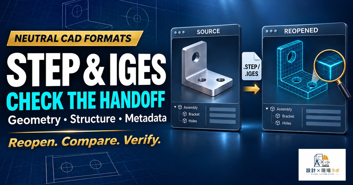
The single change that reduced translation-related problems most dramatically in my own work was building a mandatory verification step before sending any translated file out, rather than trusting a successful export as proof of a good file. My routine now includes reopening the exported STEP or IGES file in a neutral viewer separate from the originating CAD system, checking for open edges or gaps using a surface analysis tool, and comparing a handful of critical dimensions against the source model to confirm nothing shifted during translation.
This takes perhaps fifteen minutes on a typical part and closer to an hour on a complex surface model, and early in my career I resented that time as overhead the schedule could not afford. I have since come to see it as far cheaper than the alternative, having watched a missed translation error cost a supplier a full day of failed machining attempts on a part that looked flawless in every screenshot anyone had checked before it left our system.
Practical Guidelines I Now Follow on Every Handoff
After two decades of moving files between CATIA, NX, and SolidWorks environments, my working rules have become fairly simple even if they took a long time to earn. I default to STEP AP214 whenever both systems support it, reserve IGES for cases where a partner’s legacy software genuinely requires it, and always confirm the export tolerance setting rather than trusting whatever the software defaults to. I verify assembly structure separately from geometry rather than assuming it survives translation, and I never release a translated file without opening it independently first to check for the kind of invisible gaps that caused real problems earlier in my career.
None of these habits are complicated, but they were all earned through a specific failure I would rather not repeat. Neutral file formats do their job well enough that it is easy to forget how much they are quietly not doing, and the engineers who avoid costly surprises are, in my experience, simply the ones who never stopped treating that gap as something worth checking for.


コメント