
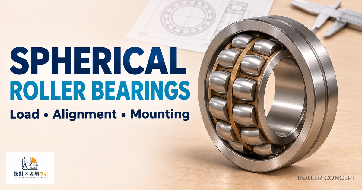
Twenty years of contract design work stationed at heavy equipment and material handling manufacturers here in Japan has given me a healthy respect for how much real-world misalignment actually shows up on a running machine, even when the drawings say everything is perfectly coaxial. Long conveyor shafts sag under their own weight, cast housings shift slightly during machining and again during thermal cycling, and foundation settling on large equipment is simply a fact of life you have to design around rather than wish away. Spherical roller bearings exist precisely because misalignment is unavoidable at a certain scale of machine, and once I started specifying them correctly instead of treating them as an oversized standard bearing, I stopped seeing the premature failures that used to plague long-shaft applications. This article covers how spherical roller bearings actually accommodate misalignment, where I choose them over other bearing types, and the mounting details — particularly around sleeves and locking — that make or break a real installation.
What Actually Makes a Spherical Roller Bearing Self-Aligning
A spherical roller bearing has two rows of barrel-shaped rollers riding on a common spherical outer raceway, which means the inner ring, cage, and rollers as a unit can rotate through several degrees relative to the outer ring axis without losing full contact along the roller length. That’s fundamentally different from a deep groove ball bearing or a cylindrical roller bearing, where misalignment concentrates load on one edge of the raceway and shortens fatigue life fast. The spherical outer raceway lets the bearing accommodate shaft deflection, housing bore misalignment, and mounting error simultaneously, typically up to somewhere around 1.5 to 2.5 degrees depending on the specific bearing series.
On a long troughing conveyor idler shaft I designed for a bulk material handling line, the shaft ran nearly four meters between bearing supports and sagged measurably under the loaded belt weight — not a huge amount in absolute terms, but enough angular deflection at the bearing locations that a rigid bearing type would have been edge-loaded within the first few weeks. Spherical roller bearings at each end let the shaft deflect naturally without transmitting that deflection into concentrated raceway stress, and that idler shaft was still running clean when I last checked in on that line years later. The self-aligning capability isn’t just a convenience feature — on a shaft that long, it’s the difference between a viable design and a bearing that fails on a predictable schedule.
Comparing Spherical Rollers to Other Self-Aligning Options
Self-aligning ball bearings exist too, and I want to be clear they’re not the same thing scaled down — they use a similar spherical outer raceway concept but with balls instead of barrel rollers, which limits their load capacity to a fraction of what a spherical roller bearing of the same size can carry. I use self-aligning ball bearings on light-duty shafts, textile machinery, and similar applications where the load is modest but alignment is still a concern. Once the load climbs into heavy machinery territory — conveyors, crushers, vibrating screens, large fans, and gearboxes — spherical roller bearings are really the only self-aligning option with enough capacity.
Tapered roller bearings and cylindrical roller bearings can carry comparable or greater load in some configurations, but neither one tolerates angular misalignment; they’re precision-alignment bearings that expect the shaft and housing to hold their designed relationship throughout the machine’s life. On a vibrating screen project, an engineer on the team initially proposed cylindrical roller bearings sized for the radial load without accounting for the screen box’s inherent flexing under dynamic operation. I pushed back and we ran the numbers on the expected angular deflection at the bearing locations under the screen’s operating vibration amplitude — it was well beyond what a cylindrical roller bearing could tolerate without edge loading, and we switched to spherical roller bearings before the design was finalized. That’s a case where catching the misalignment issue on paper saved what would have been an expensive and embarrassing field failure.
Sizing for Combined Radial and Axial Load
Spherical roller bearings can carry substantial axial load in addition to radial load, which is another reason they show up so often in heavy machinery — a single bearing often replaces what would otherwise require a separate radial and thrust bearing arrangement. The axial capacity comes from the contact angle of the barrel rollers against the spherical raceway, and different bearing series are optimized differently, some biased more toward radial capacity and others offering higher axial capacity within the same bore size.
On a vertical agitator shaft in a mixing tank, we had a meaningful combination of radial load from the mixing torque reaction and axial load from the impeller thrust plus the weight of the shaft assembly itself. Rather than stacking a separate radial and thrust bearing, we used a single spherical roller bearing series selected specifically for its higher axial capacity, which simplified the housing design considerably and reduced the overall bearing stack height. I always check the manufacturer’s combined load rating tables rather than trying to superimpose separate radial and axial calculations, because the interaction between the two isn’t a simple linear sum — the equivalent dynamic load formula they publish accounts for that interaction properly, and eyeballing it tends to be optimistic in exactly the wrong direction.
Mounting on Tapered Bores and Adapter Sleeves
A huge fraction of the spherical roller bearings I specify use a tapered bore rather than a straight bore, mounted either directly on a tapered shaft seat or, more commonly in retrofit and heavy machinery work, on a cylindrical shaft using an adapter sleeve. The adapter sleeve approach is genuinely elegant for large shafts because it lets you mount and dismount the bearing without needing a precision-ground tapered shaft section, and the internal clearance gets set by driving the bearing up the taper by a controlled amount rather than relying on an interference fit alone.
I ran into a costly lesson on this early in my career on a large fan shaft rebuild. The bearing was mounted on an adapter sleeve, and the technician doing the rebuild tightened the locknut to a torque value pulled from a generic table rather than the specific reduction-in-radial-clearance method the bearing manufacturer specified for that bearing size. The bearing ended up with excessive internal clearance because it hadn’t been driven far enough up the taper, and under load the rollers skidded rather than rolled properly during startup, generating enough heat to discolor the grease within days. We had to pull the bearing, inspect it, and remount it correctly using a feeler gauge to measure the radial clearance reduction directly rather than trusting torque alone. Since then, every adapter-sleeve-mounted spherical roller bearing I detail specifies the clearance reduction method explicitly on the drawing, with the target clearance value called out, rather than leaving it to a generic torque spec that doesn’t actually control the parameter that matters.
Housing Design and Accommodating Thermal Growth
Because spherical roller bearings are so often used on long shafts in heavy machinery, thermal growth of the shaft becomes a real design consideration, and the housing arrangement needs to account for it deliberately. My standard approach is a locating bearing at one end of the shaft, fully constrained axially, paired with a non-locating bearing at the other end that’s free to float axially within its housing to absorb thermal expansion without generating internal preload.
On a rotary kiln support roller assembly, we initially detailed both bearing housings as fully axially located, reasoning that the shaft was short enough that thermal growth wouldn’t matter much. Once the kiln got up to operating temperature, the axial growth was enough to generate a measurable preload across both bearings, and the resulting heat generation became self-reinforcing — hotter bearings meant more growth, which meant more preload, which meant more heat. We converted one housing to a floating arrangement using a spherical roller bearing with a cylindrical outer surface that could slide axially within the housing bore, and the preload problem disappeared immediately. It’s a mistake I only had to make once, but it taught me to treat the locating versus non-locating housing decision as mandatory analysis on any shaft with meaningful length or operating temperature rise, not an afterthought to be settled by habit.
Field Inspection and Failure Signatures
Spherical roller bearings fail in some visually distinctive ways that I’ve learned to read during teardown inspections, and recognizing them has saved time diagnosing repeat failures on machines I’ve supported over the years. Skidding damage from insufficient preload or clearance issues shows up as smeared, discolored streaks across the roller surface rather than the classic spalling pitting pattern of a normally fatigued bearing. Excessive misalignment beyond the bearing’s rated range, which can happen even on a self-aligning bearing if the housing bore itself is badly out of tolerance, shows up as uneven wear concentrated at one end of the roller row rather than distributed evenly across both rows.
On a crusher drive shaft that kept failing on a roughly nine-month cycle, well short of its calculated life, the failure pattern on successive teardowns consistently showed uneven wear on one roller row only. That pointed us away from a load or lubrication problem and toward a housing bore alignment issue, which turned out to trace back to a shim pack under one bearing pedestal that had compressed unevenly over time. Replacing the shim arrangement with a single machined spacer and re-verifying the bore alignment with a laser alignment tool resolved the repeat failures completely. Reading the wear pattern correctly cut what could have been months of trial-and-error troubleshooting down to a single focused inspection.
Reference
This is one small piece of a much larger toolkit for fits, stresses, and joint design that most mechanical engineers end up relying on.
Shigley’s Mechanical Engineering Design
As an Amazon Associate I earn from qualifying purchases.


コメント