
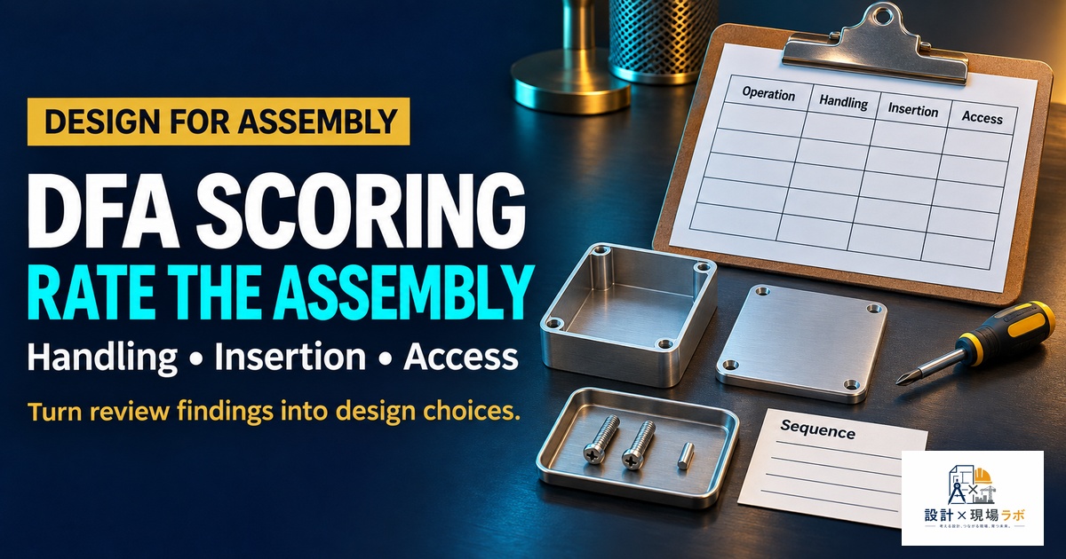
I have spent twenty years as a contract mechanical designer stationed inside the engineering departments of major manufacturers in Japan, and if there is one lesson that gets repeated in nearly every project I touch, it is this: assembly difficulty is invisible on a CAD screen until someone actually tries to build the thing. A part looks perfectly reasonable rotated on a monitor, but the moment it has to be threaded past a wiring harness by a technician wearing gloves, on a line that runs at a fixed takt time, the design reveals every flaw nobody scored for. Design for Assembly, or DFA, exists precisely to catch these problems on paper instead of on the floor. Over the years I have used several scoring methods, from the formal Boothroyd-Dewhurst approach to simplified in-house checklists cobbled together by production engineering teams, and each has taught me something different about what “difficulty” actually means. This article walks through the scoring frameworks I have relied on, where they succeed, and where I have seen them quietly fail.
- Why Assembly Difficulty Needs a Number, Not a Feeling
- The Boothroyd-Dewhurst Method and Why I Still Use It
- Simplified In-House Checklists and Their Trade-offs
- Building a Scoring Table That Matches Your Actual Production Line
- Turning Scores Into Design Decisions, Not Just Reports
- Where DFA Scoring Breaks Down and How I Compensate
Why Assembly Difficulty Needs a Number, Not a Feeling
Early in my career I worked on a compact actuator housing where the mechanical lead insisted a particular sub-assembly was “easy to put together” because he had personally snapped the prototype together on his desk in under a minute. When the parts reached the pilot line, the average build time was closer to four minutes, and the rejection rate for a snap-fit tab was nearly 8%. The lead was not lying; he was simply wrong in a very human way. He had good hand-eye coordination, no gloves, no time pressure, and he already knew exactly which orientation worked because he had designed it. A DFA score exists to strip out that personal bias and replace it with a repeatable estimate that a completely different person, with completely different skills, can arrive at using the same drawing.
The core idea behind most scoring systems is to break a design down into discrete assembly operations, then assign each operation a numeric penalty based on handling difficulty and insertion difficulty. Handling difficulty asks whether a part is easy to pick up and orient — is it symmetric, does it tangle with other parts, does it need two hands. Insertion difficulty asks whether, once oriented, the part goes into place without resistance, without needing a tool, without needing to hold something else out of the way at the same time. Add these penalties across every part in the assembly, and you get a total that lets you compare one design concept against another before either one exists as hardware.
The Boothroyd-Dewhurst Method and Why I Still Use It
The Boothroyd-Dewhurst (B-DFA) method is the one most engineers encounter first, usually through a textbook table with rows for handling codes and insertion codes, each scored zero through nine. I was skeptical of it the first time a quality manager handed me the worksheet, because it looked like the kind of academic exercise that gets abandoned after one project. But I have kept using a version of it because it forces a specific discipline: for every single part, you must ask “does this part really need to exist separately, or could it be combined with something else?” That question alone has killed more unnecessary fasteners in my designs than any other single habit.
On a control panel bracket assembly I worked on for an industrial equipment maker, running the B-DFA worksheet on a fourteen-part bracket stack-up revealed that three of those parts existed only because an earlier revision needed field adjustability that had since been eliminated by tightening a machining tolerance elsewhere. The theoretical minimum part count calculation, which B-DFA forces you to compute explicitly, showed we could get to nine parts. We ended up at ten after arguing about serviceability, but that was still a 30% part reduction with a corresponding drop in assembly time of close to 40 seconds per unit. Multiplied across an annual production volume in the tens of thousands, that number got management’s attention in a way that “this feels easier to build” never would have.
The weakness of B-DFA, and I say this after using it on dozens of assemblies, is that the scoring tables were built around manual assembly of small-to-medium mechanical and electromechanical products, largely in a Western manufacturing context from the 1980s. When I apply it to something like a large welded frame or a hydraulic manifold with heavy castings, the handling codes start to feel disconnected from reality — lifting a 20 kg casting with a hoist is a completely different kind of “difficulty” than picking up a small plastic clip, and the standard tables do not distinguish well between them. I have had to supplement the base method with custom penalty factors for weight class and required lifting aids on every heavy-assembly project.
Simplified In-House Checklists and Their Trade-offs
Not every project has the time budget for a full B-DFA worksheet, and I have worked at more than one manufacturer that developed its own simplified checklist instead. A typical version I used at one automotive-adjacent supplier scored each part on a 1-to-5 scale across four categories: orientation, insertion force, fastening method, and visibility during assembly. It is much faster to fill out — a competent designer can score a twenty-part assembly in under an hour rather than the half-day a full B-DFA analysis can take — but it sacrifices the theoretical minimum part count calculation that I found so valuable on the bracket project above.
I once ran into a case where this trade-off actually hid a real problem. A subassembly scored well on the simplified checklist because each individual part was easy to handle and easy to insert — nothing scored worse than a 2 out of 5 in any category. But the checklist had no mechanism for capturing sequence dependency, and it turned out the assembly required a specific seven-step order where step 4 had to be completed before step 2 was fully torqued, because torquing step 2 first blocked tool access for step 4. No single part was hard to assemble; the sequence itself was the problem. After that experience I started adding a fifth column to every simplified checklist I use: a simple yes/no flag for “does this operation depend on the state of a non-adjacent operation,” which at least prompts someone to think about sequence even in a quick pass.
Building a Scoring Table That Matches Your Actual Production Line
| Factor | What It Measures | Typical Score Range | Where I’ve Seen It Matter Most |
|---|---|---|---|
| Handling | Symmetry, tangling, size for gripping | 0-9 (B-DFA scale) | Small fasteners, springs, clips |
| Insertion | Resistance, alignment, obstruction | 0-9 (B-DFA scale) | Press-fits, snap-fits, blind mating |
| Fastening method | Screws vs. snaps vs. welds vs. adhesive | 1-5 (custom scale) | High-volume consumer products |
| Orientation ambiguity | Can the part go in more than one way | Pass/fail flag | Symmetric-looking but polarized parts |
| Tool access | Clearance for driver, wrench, or gun | Pass/fail flag | Dense electromechanical enclosures |
| Sequence dependency | Does order matter beyond adjacency | Pass/fail flag | Multi-stage torque or bonding operations |
I built a table close to this one after the sequence-dependency incident, and I now customize the weighting depending on the production context. On a line with skilled, experienced operators doing low-volume, high-mix work, I weight tool access and sequence dependency more heavily, because those are the factors that create errors when an operator switches between product variants all day. On a high-volume line with unskilled or rotating labor, I weight orientation ambiguity and insertion force more heavily, because those factors are what generate defects when someone has done the same motion three thousand times that shift and their attention has drifted.
Turning Scores Into Design Decisions, Not Just Reports
A DFA score that lives in a spreadsheet and never changes a drawing is worthless, and I have seen this happen more often than I would like to admit. On one project, a full DFA analysis was completed and presented in a design review, everyone nodded, and then the design proceeded unchanged because the schedule pressure to release drawings outweighed the recommendation to eliminate two fasteners. Six months later, when the line was running below the target cycle time, the same DFA report got pulled back out, and the fix that had been “too disruptive” earlier suddenly became urgent. The lesson I took from that is to attach a DFA score threshold to the design review gate itself, not just present it as informational. On subsequent projects I pushed for a rule where any part scoring above a set penalty threshold required either an engineering justification memo or a design change before drawings could be released for tooling.
I also learned to run the scoring exercise with someone from production or quality in the room, not just other designers. Designers tend to underscore insertion difficulty because we mentally simulate the assembly with perfect information about part orientation — we already know which way it goes. A production technician looking at the same drawing cold will catch orientation ambiguity that an engineer walks right past. On a fan assembly redesign, our internal team scored a bearing housing as low-difficulty, but a technician immediately asked “how do I tell the front from the back on the line,” which was a fair question given the part was nearly symmetric except for a 2mm chamfer visible only from one angle. We added a molded arrow to the part, a five-minute mold change, that eliminated a defect mode we had not even scored properly in the first place.
Where DFA Scoring Breaks Down and How I Compensate
No scoring method I have used captures everything, and I want to be honest about the gaps rather than present DFA as a solved problem. Cosmetic assembly — where a part must not only fit but must fit without visible gaps, scratches, or misalignment on a customer-facing surface — is poorly handled by standard handling and insertion codes, because a part can score perfectly on physical assembly difficulty while still requiring careful, slow handling to protect a finish. I add a separate cosmetic-sensitivity flag to any assembly with visible surfaces, and I treat it as a hard override on cycle time expectations regardless of what the numeric score says.
Electrical and pneumatic connections are another persistent gap. Standard mechanical DFA tables were built around rigid parts mating with rigid parts, and they do not model the difficulty of routing a flexible cable or a hose through a constrained path, which depends heavily on cable stiffness, bend radius, and the exact geometry of neighboring components — none of which reduce cleanly to a handling code and an insertion code. On a compressor unit with six pneumatic lines threading through a tight chassis, I ended up building a full-scale foam mockup specifically to time cable and hose routing by hand, because the numeric scoring system simply had no vocabulary for that kind of difficulty. That mockup exercise, crude as it was, caught a routing conflict that no spreadsheet would have found, and it is a reminder that DFA scoring is a tool for catching the problems it was built to catch — it is not a substitute for physically handling a representative model before tooling commits the design to steel.


コメント