
I still remember the phone call from a fabrication shop supervisor, not angry exactly, but clearly exasperated, explaining that my part drawing had specified a bend orientation that fought against the material’s grain direction on every single one of forty panels in the order, and that half of them had cracked at the bend line during forming. I had designed the part correctly by every functional requirement, the geometry was right, the tolerances were right, but I had never once thought about which way the steel coil had been rolled. That call happened over fifteen years ago and it fundamentally changed how I think about sheet metal design. Design for manufacturability in sheet metal is a discipline that rewards designers who understand the actual physical process happening on the shop floor, not just the geometry in the CAD model, and after two decades working alongside fabricators at several manufacturing sites in Japan, I want to share what I have learned about nesting, grain direction, and the dozens of small decisions that separate an efficient sheet metal part from an expensive one.
- Grain Direction and Bend Cracking
- Understanding Nesting and Why It Is Not Just the Fabricator’s Problem
- Standardizing Hole Sizes and Feature Dimensions
- Bend Relief, Corner Design, and Avoiding Tearing
- Material Utilization and Part Family Nesting
- Coil Width, Sheet Size, and Designing to Standard Stock
- Building the Feedback Loop With the Fabrication Shop
- Reference
Grain Direction and Bend Cracking
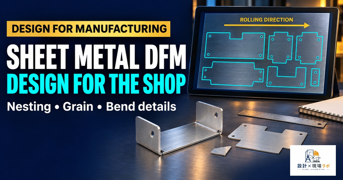
Sheet metal coil is rolled in one direction during manufacturing, and that rolling process aligns the material’s internal grain structure, which in turn affects how the material behaves when you bend it. Bending parallel to the grain direction concentrates stress along that aligned grain structure and significantly increases the risk of cracking, especially on tighter bend radii or higher-strength materials. Bending perpendicular to, or across, the grain direction distributes that stress more evenly and dramatically reduces cracking risk.
After the incident that started this article, I began specifying grain direction explicitly on every sheet metal drawing where bend orientation mattered, not just noting the material spec but adding a grain direction arrow on the flat pattern relative to the primary bend lines. On a later project involving a high-strength low-alloy steel bracket with multiple bends at different angles, I worked with the fab shop early to lay out the flat pattern so that the most critical, tightest-radius bend ran perpendicular to grain, while a less critical, more generous bend was allowed to run more parallel to grain since the risk there was lower. That kind of trade-off is only possible if you are thinking about grain direction during the design phase, because once a part is nested and cut, the orientation is locked in. As a general rule of thumb I still use today, for any bend radius tighter than about twice the material thickness, I insist on cross-grain bending wherever the part geometry allows it, and for higher-strength materials I extend that caution to more generous radii as well.
Understanding Nesting and Why It Is Not Just the Fabricator’s Problem
For years I assumed nesting, the process of arranging multiple part outlines on a sheet or coil to minimize wasted material, was purely the fabricator’s concern, something that happened after my drawing left my hands. I have since learned that a designer’s choices about part outline, orientation flexibility, and hole placement have an enormous effect on how efficiently a part can actually nest, and that treating nesting as entirely downstream leaves real savings on the table.
On a sheet metal enclosure project with an irregular trapezoidal outline, I had originally dimensioned the part with a fixed orientation assumption baked into how I toleranced a few critical hole positions relative to one edge. When the fabricator ran nesting software against that outline, the irregular shape combined with my fixed-orientation tolerancing meant parts could only nest one way, leaving significant unused material between parts on every sheet, close to 30 percent scrap by their estimate. Working with them, we found that a small design change, relaxing the tolerance reference on those holes from one specific edge to a symmetric datum scheme, allowed the nesting software to flip and rotate the part freely, interlocking trapezoidal shapes against each other and cutting scrap to under 15 percent. That is a real material cost difference across a production run of any meaningful volume, and it came entirely from a dimensioning decision, not from anything about the part’s functional geometry.
Standardizing Hole Sizes and Feature Dimensions
One of the simplest, least glamorous things I have done to reduce cost and improve manufacturability across sheet metal designs is aggressively standardize hole sizes and other repeated features within a single part and across a product family. Early in my career, I would specify whatever hole size a given fastener or clearance requirement called for exactly, which on a moderately complex enclosure could mean six or seven different hole diameters scattered across the part.
I learned from a punch press operator that every unique hole size on a part potentially requires a distinct tool station or a tool change, and that consolidating hole sizes where the functional difference did not actually matter, using a single clearance hole size for multiple fastener types that could tolerate slightly more clearance, for instance, directly reduced tooling changeovers and punch press cycle time. On a control panel redesign, I went through the drawing and consolidated seven distinct hole diameters down to three without compromising any functional requirement, and the shop reported a meaningful reduction in setup time per batch. This is the kind of change that never shows up as an exciting engineering achievement, but it compounds across every production run for the life of the part.
Bend Relief, Corner Design, and Avoiding Tearing
Corners and bend relief cutouts are another area where a design that looks perfectly reasonable in CAD can cause real problems on the shop floor if the designer has not thought through the actual forming process. I once designed a chassis part with two bends meeting close to a corner, without adding a bend relief cutout between them, reasoning that the corner geometry looked clean and the material would simply flow around it. During forming, the material tore right at that corner because the two bend lines’ deformation zones overlapped and had nowhere to relieve the resulting stress.
Since then, I follow a general design rule of adding a relief cutout, sized at minimum to the material thickness though I typically use somewhat more for added margin, at any location where two bend lines intersect or come close to intersecting near a corner. I also pay close attention to minimum distance from a bend line to an adjacent hole or cutout, generally keeping features at least three to four times material thickness away from a bend line to avoid distortion during forming. These are not arbitrary rules I invented, most sheet metal design references publish similar guidelines, but I did not internalize why they mattered until I had personally seen the torn corner on a part I had designed with what I thought was clean, minimal geometry.
Material Utilization and Part Family Nesting
Beyond nesting an individual part efficiently on its own sheet, real scrap reduction often comes from thinking about how a part fits into a broader family of parts that get cut from the same material batches. On a product line with several enclosure sizes sharing the same gauge and grade of steel, I worked with the fabricator to review how our various part outlines nested together when cut from common stock sheets rather than analyzing each part’s material utilization in isolation.
We found that two of our smaller bracket parts, originally designed with slightly different corner radii for no strong functional reason, nested extremely poorly next to our larger enclosure panels, leaving irregular scraps that were too small to use for anything else. Standardizing those two brackets to a common corner radius that matched a corner feature already present on the larger panel allowed the nesting software to interlock the smaller parts into what had previously been wasted material around the larger panel’s cutouts. Across a full production run, that single geometric alignment recovered enough material to meaningfully reduce our steel purchasing volume. This kind of gain requires looking at your part not as an isolated design but as one member of a family that will physically share sheet stock with other parts, which is not how most engineers, myself included for a long time, naturally think about individual part design.
Coil Width, Sheet Size, and Designing to Standard Stock
A mistake I made more than once early in my career was designing a part’s overall envelope dimension without checking it against standard sheet or coil widths available from the mill, resulting in parts that required custom slit widths or generated unusually wasteful remnants from standard stock sizes. On one enclosure design, my overall panel width came out to a dimension that was just a few millimeters over a common standard sheet width, forcing the fabricator to either special-order a wider custom slit width at a premium or accept significant waste cutting from the next standard size up.
I now check my overall part envelope dimensions against the fabricator’s standard stock sizes before finalizing a design, and where a part dimension sits just slightly over a standard breakpoint, I look hard at whether a small design change, a slightly reduced flange width, a modified corner treatment, could bring the part back under that breakpoint without sacrificing function. It sounds like a trivial check, but the cost difference between standard stock and custom-slit or oversized stock can be substantial, and it is entirely avoidable with about five minutes of checking against a supplier’s stock size chart during the design phase rather than discovering the problem after tooling and quoting are already underway.
Building the Feedback Loop With the Fabrication Shop
Every genuinely useful lesson in this article came from a fabricator, a punch press operator, or a shop supervisor telling me something my formal engineering education had never covered, and the single highest-leverage change I made in my own practice was building a deliberate habit of walking the shop floor and asking questions rather than treating manufacturability as something I could fully capture from a design guide. On one project, I made a point of sitting with the press brake operator for an afternoon while a new bracket design went through its first production run, watching in real time as minor adjustments got made to bend sequence and part handling that were never going to show up in any drawing review.
That afternoon taught me more about practical sheet metal DFM than months of reading specifications ever had, and it reshaped how seriously I now take shop floor input during the design phase rather than after a part is already in trouble. Twenty years into this career, my honest view is that DFM for sheet metal cannot be fully learned from a checklist, though the checklists genuinely help and I follow them closely. It has to be learned partly by standing next to the machine that actually forms the metal and paying close attention to what happens when your clean CAD geometry meets the physical reality of a coil of steel with a grain direction, a press brake with a minimum bend radius, and a nesting algorithm trying to make the most of every square centimeter of material.
Reference
For the shop-floor numbers behind a manufacturing decision, a dedicated machinist’s reference is hard to beat.
As an Amazon Associate I earn from qualifying purchases.


コメント