
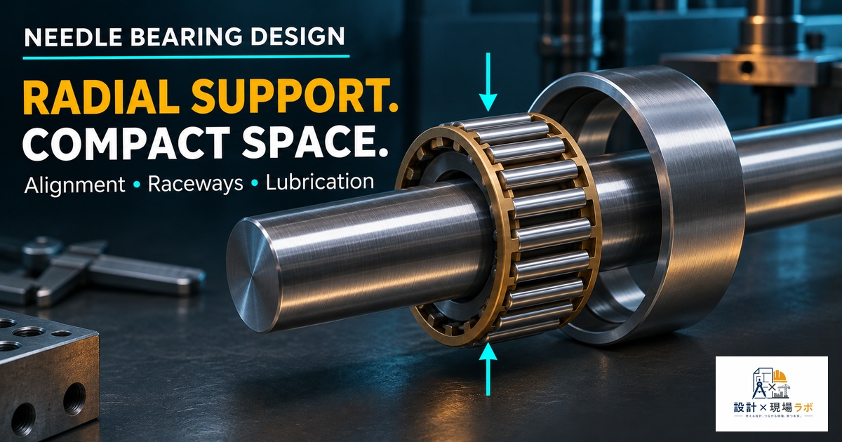
Twenty years of designing mechanisms for major manufacturers here in Japan has taught me that the projects with the tightest radial envelopes are almost always the ones where the load is highest — rocker arm pivots, planetary gear pins, compact hydraulic pumps, and small robotic joints all seem to conspire to demand more load capacity in less diametral space than any reasonable person would expect. That’s exactly the niche needle roller bearings exist to fill, and I’ve come to rely on them constantly, but they come with enough quirks and failure modes that I still see engineers misuse them regularly. This article covers how I select and detail needle bearings on real designs — where they earn their keep, where they fall apart, and the mounting and lubrication details that determine whether a needle bearing lasts the life of the machine or scores itself to death in the first few thousand hours.
Why Needle Bearings Win the Space Argument
The entire value proposition of a needle roller bearing comes down to the rollers themselves — they’re long and thin relative to their diameter, typically with a length-to-diameter ratio of 2.5 or more, compared to a cylindrical roller bearing where the rollers are closer to square in cross-section. That geometry lets a needle bearing carry a radial load comparable to a much larger cylindrical roller bearing while using a fraction of the radial cross-section, because the load capacity comes from the total contact line length of the rollers rather than from a large roller diameter.
On a compact hydraulic gear pump I worked on, the drive shaft support had to fit inside an OD constrained by the existing pump housing casting, which we weren’t allowed to modify because it was a shared part across three pump variants. A standard ball bearing sized for the radial load from the gear mesh simply wouldn’t fit in the available radial space. Switching to a drawn cup needle roller bearing dropped the radial cross-section by more than half compared to the ball bearing option while still meeting the load and life requirements, and it let us keep the shared housing casting unchanged, which saved the tooling cost of a new casting entirely. That’s the kind of problem needle bearings solve better than almost anything else in the catalog.
Types of Needle Bearings and When I Use Each
Drawn cup needle bearings are the ones I reach for most often because they’re inexpensive and press directly into a housing bore, which makes them attractive for high-volume production parts. I’ve used them extensively in gearbox idler shafts and small motor reduction stages where the housing bore can be held to a reasonable tolerance and the bearing doesn’t need to be removed for service.
Needle roller bearings with a machined ring are the step up when the application needs higher precision, higher load capacity, or the ability to be dismounted and reinstalled without damaging the bearing. On a robotic gripper joint, we specified a machined-ring needle bearing specifically because the joint needed to be serviceable in the field — a drawn cup bearing, once pressed in, is essentially a one-way installation, and trying to pull one out for a warranty repair usually damages the housing bore.
Needle roller and cage assemblies, which have no inner or outer ring at all, are the option I go to when the shaft or housing itself can serve as one of the raceways, because eliminating the ring altogether shrinks the radial envelope even further. I used this exact configuration on a planetary gear set where the planet gear pin doubled as the inner raceway — hardening and grinding the pin surface to bearing-raceway quality was more expensive per part than a standard ground shaft, but it let the planet gear outside diameter grow larger within a fixed carrier envelope, which was the actual design driver.
Load Capacity and the Misalignment Problem
Needle bearings have excellent radial load capacity for their size, but that capacity comes with an important caveat: they are extremely intolerant of misalignment and essentially cannot carry any axial load on their own. Because the rollers are long relative to their diameter, even a small angular misalignment between the shaft and housing concentrates load at one end of each roller instead of spreading it along the full contact line, which dramatically shortens fatigue life at that edge.
I learned this the hard way on an early project — a conveyor idler roller supported on needle bearings at each end. The mounting bracket tolerance stack allowed just over half a degree of misalignment between the two bearing bores, which seemed trivial on paper. In service, the rollers on one end developed edge spalling within about four months, well short of the multi-year life we’d calculated assuming perfect alignment. The fix ended up being tighter positional tolerancing on the bracket bores and a line-boring operation to guarantee coaxiality, rather than a bearing change — the bearing itself was correctly sized, the housing just wasn’t holding up its end of the deal. Since that project, I always call out a coaxiality tolerance between needle bearing bores on the drawing rather than assuming that two independently toleranced holes will end up aligned enough.
Because needle bearings can’t take meaningful axial load, I pair them with a separate axial locating feature — a shoulder, snap ring, or a small thrust washer — on essentially every application, and I make sure that axial feature isn’t relying on the needle bearing itself for any part of its function.
Shaft and Housing Surface Requirements
One detail that trips up a lot of designers coming from ball bearing experience is that many needle bearing configurations, particularly the full complement cage-and-roller type, use the shaft or housing bore directly as a raceway. That means the mating surface needs raceway-quality hardness, surface finish, and roundness — not just a nominally toleranced shaft.
On a small planetary reduction gearbox, I specified a shaft that used the needle bearing cage-and-roller assembly directly against the shaft OD, and the drawing initially called out the same general shaft tolerance and finish we used everywhere else on that assembly, roughly Ra 1.6. The bearing manufacturer’s application data for that specific bearing called for something closer to Ra 0.4 with a minimum surface hardness of 58 HRC to a specified case depth. We caught the mismatch during design review, thankfully before parts were cut, but I’ve since made it a standing habit to pull the manufacturer’s mating part specification sheet for any bearing that uses the shaft or housing as a raceway, because those requirements are not something you can safely infer from general machine shop practice.
Cage Design and Full Complement Tradeoffs
Needle bearings come in both caged and full-complement configurations, and the choice between them is a real engineering tradeoff, not just a cost decision. A full-complement bearing packs the maximum number of rollers into the available space with no cage separating them, which maximizes radial load capacity for a given envelope — sometimes by a meaningful margin over a caged version of the same nominal size. The cost is friction: adjacent rollers in a full-complement bearing rub against each other because they’re spinning in opposite directions at the contact point, generating heat and limiting the practical speed rating.
On a high-speed spindle accessory drive, we initially spec’d a full-complement needle bearing to squeeze out extra load margin, but during testing the bearing ran noticeably hotter than predicted and the speed was well above what full-complement needle bearings are generally suited for. Swapping to a caged version with a slightly lower dynamic load rating solved the heat problem completely, and because the actual operating load had margin to spare, the small reduction in capacity didn’t matter in practice. The general rule I follow now is full complement for low-speed, high-load, space-constrained applications like rocker arms and cam followers, and caged for anything running at meaningful speed.
Lubrication in a Tight Envelope
Lubricating a needle bearing is harder than lubricating a standard ball or roller bearing precisely because the same tight radial envelope that makes needle bearings attractive also leaves very little room for grease reservoirs or oil passages. On a compact right-angle gearbox, the needle bearings supporting the input pinion were originally lubricated by splash from the gear mesh alone, with no dedicated feed. In the field, units running at low duty cycle in cold ambient conditions weren’t getting adequate splash lubrication during startup, and we saw a cluster of early bearing failures traced back to that starvation period before the gear oil warmed up and started splashing properly.
The fix was adding a small machined groove and a cross-drilled oil feed hole directly into the housing to guarantee a minimum oil film at the bearing regardless of splash conditions, which is a modification I now build into any right-angle or vertical-shaft gearbox design from the start rather than waiting for a field failure to teach me the lesson again. For grease-lubricated needle bearings, I pay close attention to the fill percentage — overfilling a needle bearing with grease is a surprisingly common cause of overheating because there’s so little internal void volume for the grease to churn in compared to a ball bearing of similar size, so the manufacturer’s recommended fill percentage, usually somewhere around 30 to 50 percent of the free space, is not a number I round up on.
Reference
This is one small piece of a much larger toolkit for fits, stresses, and joint design that most mechanical engineers end up relying on.
Shigley’s Mechanical Engineering Design
As an Amazon Associate I earn from qualifying purchases.

コメント