
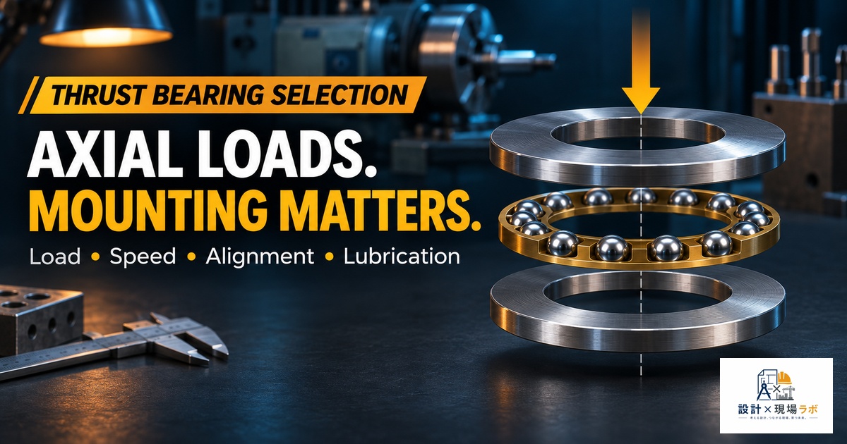
I’ve spent twenty years as a contract mechanical designer bouncing between assembly lines, packaging machinery, and heavy equipment shops in Japan, and if there’s one component that gets underestimated more than any other, it’s the thrust bearing. Engineers spend hours agonizing over radial bearing selection because that’s what the shaft “obviously” needs, and then they bolt on whatever thrust washer or single-row ball thrust bearing happens to be in the standard parts catalog without running a single load calculation. I’ve watched that shortcut turn into a machine down for three shifts more times than I’d like to admit. This article walks through how I actually approach thrust bearing selection on a real project — where the axial loads come from, how to size the bearing properly, and the mounting details that separate a bearing that lasts five years from one that scores its raceway in five months.
Where Thrust Loads Actually Come From
Before you can select a thrust bearing, you have to be honest about where the axial force is originating, and in my experience this is the step most junior designers skip. On a vertical pump shaft I worked on early in my career, the axial load wasn’t just the weight of the impeller and shaft hanging down — it was dominated by the hydraulic thrust generated by the pressure differential across the impeller, which was nearly four times the dead weight. I made the mistake of sizing the thrust bearing off the static weight alone during the first pass, and when we got the unit on the test stand, the temperature rise on the bearing housing told us immediately something was wrong.
Helical gears are another classic source that people forget to add up correctly. Every helical gear mesh produces an axial thrust component proportional to the tangential force and the tangent of the helix angle, and on a multi-stage gearbox those thrust components either add or partially cancel depending on the hand of each gear. I once worked on a two-stage speed reducer where the original design had both helical stages cut with the same hand, which stacked the axial loads instead of letting them partially offset. Reversing the hand on the second stage cut the required thrust capacity nearly in half, and we didn’t need a bigger bearing at all — we needed a smarter gear design. The lesson I took from that project is that thrust bearing selection often starts upstream, in the gear or screw design, not at the bearing catalog.
Ball Thrust Bearings vs. Roller Thrust Bearings
Once you know the magnitude and direction of the axial load, the next decision is ball versus roller. Single-direction ball thrust bearings are cheap, low-friction, and fine for moderate loads at moderate to high speed, but they cannot take any radial load and they don’t like misalignment at all — even a few tenths of a millimeter of angular misalignment will concentrate the load on one side of the raceway and shorten life dramatically. I use them on things like rotary table indexers and light packaging machine spindles where the load is predictable and purely axial.
Cylindrical roller thrust bearings and tapered roller thrust bearings come into play once the load climbs into territory a ball bearing can’t handle in a reasonable envelope. On a hydraulic press project, we needed to support close to 80 kN of axial load on a rotating platen with a fairly tight axial envelope, and a ball thrust bearing of the required capacity would have needed a bore far larger than the shaft could accommodate. We switched to a cylindrical roller thrust bearing, which handled the load in a much more compact stack height because rollers carry load over a line contact rather than a point contact. The tradeoff is friction and speed limit — roller thrust bearings run hotter and have a lower limiting speed than an equivalent ball bearing, so I always double check the DN value (bore diameter in mm times RPM) against the manufacturer’s speed rating before locking in the selection.
Spherical roller thrust bearings deserve a separate mention because they’re the only thrust bearing type that can accept meaningful radial load alongside the axial load, and they self-align through several degrees, which has bailed me out on more than one badly toleranced housing bore.
Calculating Axial Load Capacity the Right Way
The number that matters isn’t the catalog’s static load rating in isolation — it’s the relationship between your actual axial load, the bearing’s basic dynamic load rating, the required L10 life, and the speed. I run the standard L10 life calculation (L10 = (C/P)^p × 10^6 revolutions, with p = 3 for ball bearings and p = 10/3 for roller bearings) for every thrust bearing selection, even on what feels like a “simple” application, because eyeballing it has burned me before.
On a conveyor drive project, the customer’s spec called for a 20,000-hour design life at the rated axial load. When I ran the numbers on the bearing the previous designer had specified, it came out to roughly 6,000 hours at the actual operating load — a huge shortfall that would have meant bearing replacement every eight months in a facility running three shifts. The root cause was that the original selection had been based on the bearing’s static capacity rather than the dynamic rating at the actual operating speed, which is an easy mistake to make when you’re skimming a catalog page under deadline pressure. Bumping up one bearing size and adding a light preload to reduce internal clearance got us to 22,000 hours, comfortably over spec, without changing the housing dimensions.
I also always apply a load factor for shock or vibration if the application has any — packaging machinery with cam-driven axial motion, for instance, can see instantaneous peak loads two to three times the average, and if you size purely on average load you’ll be replacing bearings constantly.
Combined Loads and When a Thrust Bearing Isn’t Enough
Pure axial load is actually rare in real machines. Most of the time you have some combination of radial and axial load, and a dedicated thrust bearing paired with a separate radial bearing is often the right answer rather than trying to force one bearing to do both jobs. On a rotary index table I designed, we used a deep groove ball bearing to take the radial load from the drive torque and a separate cylindrical roller thrust bearing stacked underneath to take the axial load from the table’s own weight and the workpiece fixtures. Splitting the duty this way let each bearing be optimized for its actual job instead of compromising on a single combined-load bearing that would have been oversized for one direction and marginal for the other.
Angular contact ball bearings and tapered roller bearings are the other common answer when radial and axial loads are both significant and you don’t have room for a split arrangement — they’re designed from the start to take combined loading, usually mounted in pairs (back-to-back or face-to-face) to handle axial thrust in both directions. I reach for these on gearbox output shafts where the axial thrust reverses depending on whether the machine is running forward or in reverse.
Mounting Orientation and Preload
Thrust bearings are unforgiving about mounting orientation in a way radial bearings often aren’t. A single-direction thrust bearing has a stationary washer and a rotating washer, and if you install it backwards or fail to keep the shaft washer running true with the shaft, you’ll get uneven wear almost immediately. On a vertical mixer shaft, an assembly technician installed the thrust bearing upside down during a rebuild — the tight-fitting washer was supposed to be against the rotating shaft, but it ended up against the stationary housing. The machine ran for about two weeks before the bearing seized, and when we tore it down, the raceway had spalled unevenly in a pattern that immediately told us the orientation was wrong. Now I put an assembly note directly on the drawing with an arrow and a callout, because a mounting instruction buried in a bearing catalog PDF is not something I trust the shop floor to dig up during a rebuild at 2am.
Preload is the other detail that gets glossed over. A small amount of axial preload keeps the bearing from experiencing impact loading every time the direction of thrust reverses, which matters a lot on anything with reciprocating or oscillating axial motion. Too much preload, though, and you’re just generating unnecessary friction and heat. I typically work with the bearing manufacturer’s application engineer to get a specific preload number for anything beyond the simplest static-load case, because the right answer depends heavily on thermal growth of the shaft and housing, which is not something you want to guess at.
Lubrication and Speed Limits
Thrust bearings, especially roller types, are more sensitive to lubrication starvation than radial bearings because the geometry doesn’t naturally sling oil across the raceway the way a radial bearing does. On a rotary furnace application, we had a cylindrical roller thrust bearing that kept running hot despite being well within its calculated load and speed rating. It turned out the grease fitting had been placed on the low side of the housing, and gravity combined with the bearing’s own rotation was pulling grease away from the contact zone rather than into it. Relocating the fitting and adding a second relief port to let old grease purge out properly solved the overheating completely — the fix cost almost nothing but took two failed troubleshooting sessions to actually find because everyone assumed it was a load or alignment problem.
For high-speed applications, I check the reference speed rating in the catalog and de-rate further if the lubricant is grease rather than oil, since grease-lubricated thrust bearings typically top out well below their oil-lubricated speed limit. If a project needs both high speed and high axial load, I’ve had good results with oil-jet lubrication feeding directly into the bearing cage rather than relying on splash or grease pack, though that obviously adds cost and complexity that has to be justified by the application.
A Mounting Detail That Taught Me to Slow Down
The project that changed how carefully I detail thrust bearing installations was a semiconductor handling robot with a vertical ball screw axis. The thrust bearing supporting the ball screw was correctly sized, correctly oriented, and correctly preloaded on paper. What nobody caught was that the locknut securing the bearing’s inner race to the shaft was under-torqued during final assembly, so under repeated acceleration and deceleration cycles the inner race crept slightly relative to the shaft. Over a few thousand cycles that micro-fretting wore a groove into the shaft seat, which let the whole stack develop play, which in turn let the axial preload disappear entirely. The symptom on the machine was a barely perceptible positioning error that only showed up after the axis had been running for several hours — exactly the kind of intermittent problem that’s miserable to diagnose. Since that project, every thrust bearing assembly I detail gets an explicit torque value and a witness mark callout on the locknut, and I specify a locking method — tab washer, adhesive, or mechanical stake — rather than trusting torque alone to keep it in place over the life of the machine. It’s a small line item on a drawing, but it’s the difference between a bearing that quietly does its job for a decade and one that generates a support call six months after startup.
Reference
This is one small piece of a much larger toolkit for fits, stresses, and joint design that most mechanical engineers end up relying on.
Shigley’s Mechanical Engineering Design
As an Amazon Associate I earn from qualifying purchases.


コメント