
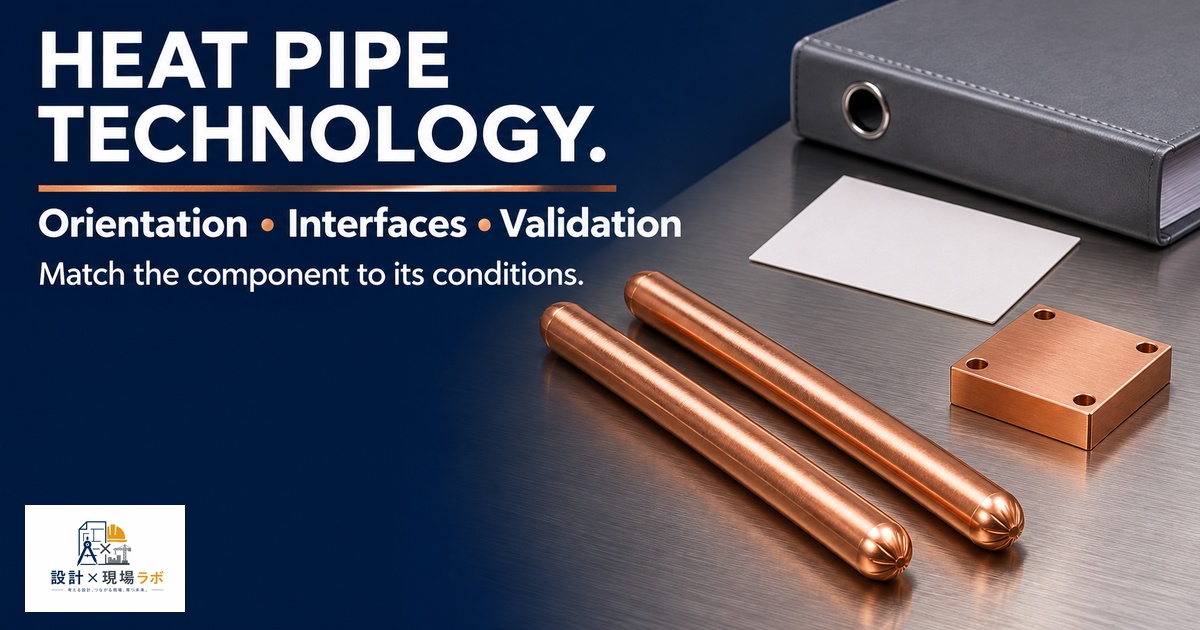
Twenty years into a career spent mostly stationed inside the design offices of large manufacturers, I’ve noticed that heat pipes are one of those components everyone assumes they understand until they actually have to spec one. On paper it looks trivial: a sealed copper tube, a bit of working fluid, and heat magically travels from a hot spot to a cooler one without a fan or a pump. In practice, getting a heat pipe to actually perform the way the datasheet promises inside a real enclosure, with real tolerances and real orientation constraints, is a different story. I’ve designed thermal solutions around heat pipes for everything from industrial servo drives to compact optical instruments, and I want to walk through what actually matters when you put one into a mechanical assembly.
How Heat Pipes Actually Work (Capillary Action and Phase Change)
A heat pipe is deceptively simple in concept. Inside a sealed, evacuated tube sits a small amount of working fluid, usually water for the temperature ranges most of us deal with, though ammonia or methanol shows up in specialty applications. At the evaporator end, near the heat source, the fluid absorbs heat and vaporizes. That vapor travels through the core of the pipe toward the cooler condenser end, where it releases its latent heat and condenses back to liquid. The liquid then returns to the evaporator through a wick structure lining the inner wall, driven by capillary action, and the cycle repeats.
What trips people up is that this isn’t conduction in the traditional sense. The effective thermal conductivity of a well-designed heat pipe can be an order of magnitude higher than solid copper, sometimes reaching the equivalent of tens of thousands of W/m·K, because the heat transport is happening through phase change and vapor movement rather than through a solid lattice. On a project involving a compact power supply enclosure, I initially sized a solid copper spreader bar to move heat from a transformer to the case wall. The mass and volume budget wouldn’t allow a bar thick enough to do the job. Swapping to a 6mm heat pipe bent into the same envelope solved the problem with a fraction of the mass, precisely because I was no longer relying on bulk conduction.
Wick Structures and Why They Matter
The wick is where most of the real engineering happens, and it’s the part that gets glossed over in vendor catalogs. Sintered copper powder wicks give you the best capillary pumping pressure and work well against gravity, which matters if your condenser ends up above your evaporator in the final orientation. Grooved wicks, machined directly into the inner wall, are cheaper and give higher permeability but weaker capillary force, so they’re best when the pipe operates horizontally or with gravity assisting flow. Mesh or screen wicks fall somewhere in between and are common in bent, flattened pipes because they tolerate deformation better than sintered structures.
I ran into this directly on a handheld diagnostic instrument where the heat pipe had to route around a battery compartment and end up with the condenser slightly below the evaporator in the worst-case orientation the user might hold the device. The original spec called for a grooved wick pipe because it was cheaper, and it worked fine on the bench where we always tested it lying flat. Once we started testing in the actual use orientations, the anti-gravity performance collapsed and junction temperatures on the driver IC crept up 15°C. Switching to a sintered wick pipe, at roughly double the unit cost, fixed it. That was a lesson in not letting the bill of materials drive a decision that should have been driven by the use case.
Sizing and Orientation Constraints
Every heat pipe has a maximum heat transport capacity, and it is not a fixed number — it depends heavily on operating temperature, pipe diameter, length, and orientation relative to gravity. Vendors publish curves showing capacity as a function of these variables, and I’ve seen more than one junior engineer pull a single wattage number off a summary table without checking that it assumed horizontal operation. If your design places the evaporator above the condenser, you are working against gravity and capacity can drop by 30 to 50 percent compared to the horizontal case.
There’s also a dry-out limit to respect. Push too much heat flux through the evaporator section, and the wick can’t return liquid fast enough to keep up with evaporation, causing localized dry-out and a sudden collapse in performance rather than a graceful degradation. This is why heat pipes are often paired with a vapor chamber or a spreader plate at the evaporator interface — spreading the heat flux over a larger footprint before it enters the pipe keeps you well clear of that limit. On one design I reviewed, a colleague had a heat pipe evaporator soldered directly to a small MOSFET footprint with no spreader, and under peak load the pipe was operating right at its dry-out threshold. We added a small copper spreader block between the component and the pipe, and the margin problem disappeared.
Heat Pipes vs Vapor Chambers vs Solid Copper
It’s worth being honest about when a heat pipe is not the right tool. Solid copper or aluminum spreaders are still the right choice for short distances and low power densities, because they’re cheaper, more robust, and have no orientation sensitivity or long-term working fluid concerns. Heat pipes earn their keep when you need to move meaningful heat over a distance of several centimeters or more, especially around obstacles, without the mass penalty of solid metal.
Vapor chambers, which are essentially flattened, two-dimensional heat pipes, are the better choice when you need to spread heat over an area rather than transport it along a line — for example, taking a concentrated hot spot from a small die and spreading it across a broad heat sink base. I’ve used both in the same assembly: a vapor chamber directly under a power module to spread the flux, feeding into heat pipes that carried the heat out to a remote fin stack near the enclosure vents. Treating these as complementary components rather than competing options usually gives the best result.
Integration Challenges in Real Assemblies
Getting a heat pipe from a datasheet into a real assembly involves several practical headaches. Bending a round heat pipe reduces its internal cross-section at the bend and can degrade capacity, typically by 5 to 15 percent depending on bend radius and how it’s formed. Flattening a pipe to fit a low-profile envelope does the same thing more severely — a heavily flattened pipe can lose a third of its rated capacity. Vendors will give you correction factors for both, and I’ve learned to always ask for them rather than assume the straight-pipe number still applies once your mechanical constraints are done with it.
Attachment method matters just as much as the pipe itself. Solder attachment to a copper base gives the lowest thermal resistance but adds cost and process complexity, particularly if you’re trying to solder a heat pipe into an aluminum housing, which requires a nickel-plated interface. Epoxy or thermal adhesive attachment is easier in production but adds a bond line that can dominate the total thermal resistance if it’s not controlled carefully. On a mid-volume product I worked on, we switched from solder to a thermally conductive epoxy purely for manufacturability, and had to bump up condenser fin area by about 10 percent to compensate for the slightly higher junction-to-ambient resistance. It was a fair trade for a process that didn’t need a reflow step in final assembly.
Failure Modes I’ve Seen in the Field
Heat pipes are generally reliable because there are no moving parts, but they aren’t immune to failure. The most common issue I’ve encountered is a slow loss of vacuum integrity at the seal, usually at the end cap weld or crimp, which lets non-condensable gas into the pipe over years of thermal cycling. This shows up as a growing dead zone at the condenser end and a gradual rise in thermal resistance that’s easy to mistake for fan degradation or dust buildup if you’re not measuring pipe wall temperature directly.
I also saw a batch quality issue once where a supplier’s charging process left slightly too little working fluid in a run of pipes. Units passed initial functional test because the shortfall wasn’t enough to cause outright dry-out at typical loads, but under sustained high-load testing in an environmental chamber, several units showed thermal runaway behavior that didn’t match the rest of the batch. Tracing it back to fluid charge variance took cutting open failed units and weighing the residual fluid against spec, which is not a fun afternoon but was the only way to confirm the root cause conclusively.
Practical Design Checklist
When I’m reviewing a heat pipe integration now, I go through a short mental checklist before signing off. First, confirm the operating orientation envelope and check the vendor’s capacity derating curve against the worst case, not the nominal case. Second, verify bend radius and flattening ratio against the correction factors, not the straight-pipe rating. Third, make sure the evaporator interface has adequate spreading area so you’re not pushing flux limits at the component footprint. Fourth, decide on attachment method early, because it affects both thermal resistance budget and manufacturing process, and changing it late in a program is expensive.
Finally, I always push for thermal validation testing in the actual worst-case orientation, not just on a bench with the assembly lying flat, because that single oversight has caused real field problems on more than one program I’ve been part of. Heat pipes are a genuinely elegant piece of engineering, but they reward careful integration and punish assumptions, which describes most passive thermal components if I’m honest about it.


コメント