
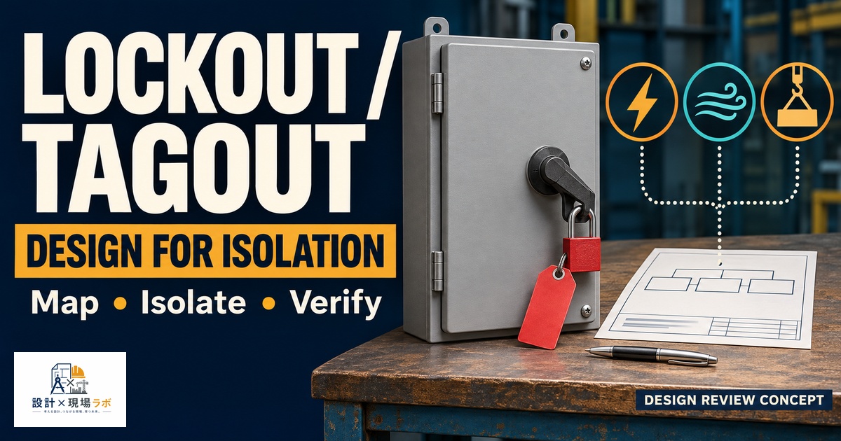
I have spent twenty years designing production machinery as a contract engineer stationed inside major manufacturing plants in Japan, and if there is one topic that separates a machine built by someone who has actually stood in front of an energized panel from one built by someone who has only seen a schematic, it is lockout/tagout. LOTO is not a sticker you add at the end of a project. It is a set of physical decisions – where the isolation point sits, how many energy sources exist, how a technician verifies zero energy – that have to be baked into the layout from the first arrangement drawing. When I review a machine that was designed without LOTO in mind, I can usually tell within five minutes, because the maintenance access panel is on the wrong side, or the main disconnect is buried behind a conveyor frame, or there are three separate air lines feeding one cylinder and no single point to isolate all of them. This article walks through the design decisions I actually use when I lay out isolation points, from energy source mapping to the paperwork that keeps a plant safety audit from turning into a shutdown order.
- Mapping Every Energy Source Before Drawing a Single Bracket
- Placing the Isolation Point Where People Actually Stand
- Designing for Multiple Simultaneous Locks
- Group Lockout Boxes and Centralized Isolation
- Verification Points: Proving Zero Energy, Not Assuming It
- Writing Procedures That Match the Physical Machine
- Retrofit Realities: Adding LOTO to an Existing Machine
Mapping Every Energy Source Before Drawing a Single Bracket
The first thing I do on any new machine, before I place a single structural member, is build an energy source map. This sounds bureaucratic, but it is genuinely the most useful hour I spend on a project. I list electrical (main power, control power, any UPS-backed circuits), pneumatic (main supply and any accumulator or receiver tank downstream that can hold pressure after the main valve closes), hydraulic, and stored mechanical energy like a raised gantry axis or a spring-loaded clamp.
On a packaging line project I worked on, the original concept had a single electrical disconnect and assumed that was sufficient. It was not, because the machine also carried a small pneumatic accumulator sized to give one extra stroke of a pusher cylinder during a power dip. If a technician killed the main disconnect and opened the guard without bleeding that accumulator, the pusher could still fire once. I only caught this because I forced myself to walk the energy map physically, tracing every line rather than trusting the P&ID. That accumulator ended up needing its own bleed valve with a visual pressure gauge right next to the main isolation point, so a technician could see zero before reaching in.
I have learned to be suspicious of any machine with more than one energy type and only one isolation device. Almost every real machine has electrical plus at least one of pneumatic or hydraulic, and each of those needs its own dedicated lockout point unless you build a combined isolation panel.
Placing the Isolation Point Where People Actually Stand
A lockout point that is technically present but physically inconvenient gets bypassed. I have seen it happen – a disconnect switch mounted on the back of a machine, facing the wall, three meters from the access door a technician actually uses. Nobody walks around to lock it out properly during a five-minute jam clearance. They reach in through the guard opening instead, because the isolation point was designed for a schematic, not a human being.
My rule now is that the primary electrical disconnect and the main pneumatic isolation valve both need to be visible and reachable from within two steps of the most frequently opened access point on the machine. On a conveyor transfer station I designed for an automotive parts line, I moved the main air isolation valve from the utility drop location the plant’s facilities team originally specified to a bracket mounted directly on the machine frame next to the operator-side access door. It cost an extra meter of air line and a mounting bracket, maybe fifteen dollars in material. But every operator I talked to during commissioning told me it was the difference between actually using it and working around it.
I also pay attention to the height and orientation of lockout hasps. If a technician needs both hands to hold a padlock and a hasp above shoulder height while also holding a jam clearance tool, they will skip it. Waist to chest height, with enough clearance around the hasp for a standard padlock body, is the target I design to.
Designing for Multiple Simultaneous Locks
Group lockout is where a lot of otherwise good designs fall apart. A single machine on a shift often has an electrician, a mechanical technician, and a line operator all needing to verify isolation at the same time, and a hasp that only accepts two padlocks becomes a bottleneck that pressures people into sharing keys, which defeats the entire purpose of individual lockout.
I standardized on multi-lock hasps rated for at least six padlocks on any isolation point serving equipment with more than one trade regularly working on it, after a plant safety coordinator at a chemical processing site pointed out during a design review that their crews routinely had four people locked out on a single reactor feed pump. That conversation changed how I spec hardware on every project since. It is a small line item on a BOM, a few dollars difference between a two-hole and a six-hole hasp, but running out of hasp capacity mid-shift is the kind of thing that generates a real incident report.
Group Lockout Boxes and Centralized Isolation
For machines with more than three or four separate energy isolation points, I have moved toward centralized lockout boxes rather than requiring technicians to walk the machine locking each point individually. A group lockout box holds a key or a captured valve handle for every isolation device on the machine, and a single master lock on the box represents the entire machine’s isolated state. Anyone doing work locks onto the box, not onto six separate devices scattered around the frame.
On a large stamping press auxiliary system I worked on, we had electrical, main hydraulic, a secondary hydraulic circuit for the die cushion, and two pneumatic supplies for the material handling robot interface. Five isolation points is too many for a technician to reliably verify one by one under time pressure. I specified a centralized box with captured-key isolation valves feeding into it, so locking one master padlock on the box guaranteed all five sources were physically isolated. This also made the periodic LOTO audit dramatically simpler, since an auditor could verify the box’s status in one look instead of tracing five separate devices.
Verification Points: Proving Zero Energy, Not Assuming It
Isolating an energy source and verifying it is isolated are two different steps, and I design for both. Electrical isolation gets a voltage-rated test point built into the panel door, positioned so a technician can check for zero volts without opening the enclosure further than the door swing. Pneumatic and hydraulic circuits get gauges downstream of the isolation valve, not just upstream, because I have seen technicians misread an upstream gauge that still showed line pressure and conclude the isolation had failed, when actually the downstream side was already at zero and the valve was doing its job correctly. Downstream gauges eliminate that ambiguity.
For stored mechanical energy – a counterweighted axis, a spring-return actuator, a raised load – I try to eliminate the hazard through design rather than relying on procedure alone. A mechanical prop or pin that physically blocks a gantry from descending is more reliable than a note in a lockout procedure that says “install safety prop before servicing.” On a vertical lift table I designed for a warehouse automation retrofit, I added a spring-loaded safety pin that automatically engaged into a rack the moment the table reached a service height, so there was no procedural step to forget. The pin had to be manually retracted to lower the table again, which meant a technician physically had to interact with the safety device to remove it, closing the loop.
Writing Procedures That Match the Physical Machine
I do not write the formal LOTO procedure documents myself in most plants, since that is usually an EHS function, but I have learned to hand off a clean isolation point list and sequence recommendation rather than leaving it to someone reverse-engineering my design from a general arrangement drawing. I provide a simple table for every machine: energy type, isolation device location, verification method, and approximate time to complete each step.
| Energy Source | Isolation Device | Location | Verification Method |
|---|---|---|---|
| Main electrical | Disconnect switch, panel-mounted | Operator access door, left side | Voltage test point, panel door |
| Control power | Secondary breaker | Inside main panel | Indicator lamp + test point |
| Pneumatic supply | Lockable ball valve | Machine frame, near door | Downstream gauge, zero reading |
| Hydraulic supply | Lockable ball valve | Pump skid | Downstream gauge, zero reading |
| Stored mechanical | Safety prop pin | Vertical axis, service height | Visual pin engagement |
This table has saved a lot of back-and-forth during commissioning, because a plant’s safety writer can sit down with it and produce an accurate procedure in an afternoon instead of walking the machine repeatedly asking me questions.
Retrofit Realities: Adding LOTO to an Existing Machine
Not every project is a clean-sheet design. A significant part of my work over the years has been retrofitting isolation capability onto older machines that predate current LOTO expectations, and this is genuinely harder than doing it right from the start. On an aging blow-molding machine I was asked to bring up to current safety standards, the original electrical panel had no dedicated lockable disconnect at all, just a breaker inside a cabinet that required a key to open the cabinet door in the first place. I added a lockable disconnect switch upstream of the panel, in a new small enclosure mounted where a technician could reach it without opening the main cabinet.
The harder problem on that job was the hydraulic system, where the original design used a single manifold with six directional valves and no isolation valve upstream at all – killing the pump only removed pressure generation, but the accumulator on that system could hold usable pressure for close to twenty minutes after shutdown. I added a manual dump valve plumbed directly from the accumulator to tank, with a placard next to it specifying the wait time and the gauge to check before proceeding. Retrofits like this take longer than people expect and often cost more than the original machine’s isolation hardware would have if it had been specified correctly at build time, which is exactly the argument I use with clients who want to skip LOTO planning on new equipment to save a few days in the schedule.


コメント