
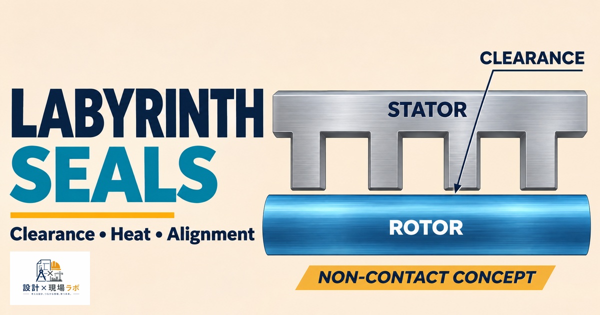
I’ve spent much of the last two decades as a contract mechanical designer working on rotating equipment at major manufacturers in Japan, and one of the recurring arguments I have with newer engineers is about why a piece of high-speed rotating machinery needs a seal that, by design, isn’t actually sealing anything tightly. Labyrinth seals leak — that’s not a defect, it’s how they’re supposed to work. What they don’t do is touch the shaft, which is exactly the point once surface speeds get high enough that a contact seal would generate unacceptable friction heat and wear itself out in a fraction of the machine’s intended life. This article walks through how I actually design labyrinth seals for high-speed applications — the flow physics that make them work, the geometry choices that matter, and a handful of field lessons about clearance and installation that I learned the expensive way.
- Why Non-Contact Sealing Becomes Necessary at High Speed
- How Labyrinth Seals Actually Restrict Flow
- Straight-Through vs. Stepped Labyrinth Geometry
- Radial Clearance: The Central Design Tradeoff
- Managing Windage and Heat Generation
- Installation and Assembly Considerations
- Combining Labyrinth Seals with Other Sealing Elements
Why Non-Contact Sealing Becomes Necessary at High Speed
Every contact seal, whether it’s a lip seal or a mechanical face seal, generates friction at the sealing interface, and friction at a rotating interface generates heat proportional roughly to the surface speed. Below a certain PV limit — pressure times velocity — that heat is manageable and a contact seal is the simpler, cheaper, more effective choice. Above that limit, the seal lip either burns up prematurely or requires so much cooling flow and material engineering to survive that it stops being practical.
On a high-speed centrifugal compressor project, the shaft surface speed at the seal location was well beyond what any elastomeric lip seal could survive for more than a few hundred hours, and mechanical face seals, while technically capable, would have added significant cost and a failure mode — face wear and seal face damage from any momentary dry running — that the customer specifically wanted to avoid on a machine that ran continuously for years between shutdowns. A labyrinth seal has no rubbing contact at all in its ideal form, so there’s no wear-out mechanism tied to running hours the way a contact seal has. That reliability profile is really the whole reason labyrinth seals dominate turbomachinery, high-speed motors, and gearbox output shafts once you get past a certain speed threshold.
How Labyrinth Seals Actually Restrict Flow
A labyrinth seal works by forcing the leaking fluid — usually air, gas, or oil mist — through a series of narrow radial clearances alternating with larger expansion chambers, and each time the fluid squeezes through a restriction and expands into a chamber, it loses velocity head as turbulent kinetic energy that gets dissipated rather than recovered. Each successive tooth adds another pressure drop, so the total number of teeth, more than any single clearance dimension, determines how much total leakage the seal allows for a given pressure differential.
I ran into a case early in my career where a labyrinth seal on a blower shaft was leaking noticeably more than the calculated value, and my first instinct was that the radial clearance had been machined oversize. The clearance measured correctly on inspection, but when I counted the actual teeth against the drawing, the seal had been manufactured with two fewer teeth than specified because of a tooling change the machine shop made without flagging it back to us. Two fewer expansion chambers doesn’t sound like much, but it meaningfully reduced the total pressure drop capability, and the leakage difference matched almost exactly what the reduced tooth count predicted. It was a good reminder that labyrinth seal performance is a system property of the whole tooth arrangement, not something you can verify by checking a single clearance dimension in isolation.
Straight-Through vs. Stepped Labyrinth Geometry
The simplest labyrinth configuration is a straight-through design, where a series of identical teeth on the rotor (or stator) face a smooth opposing surface with uniform radial clearance at each tooth. It’s easy to manufacture and works fine for moderate pressure differentials, but it has a known weakness: kinetic energy carryover between chambers. If the chambers aren’t deep enough relative to the tooth pitch, the turbulence from one restriction doesn’t fully dissipate before the flow hits the next tooth, and the seal ends up leaking more than a simple additive pressure-drop calculation would predict.
Stepped or interlocking labyrinth designs, where teeth alternate between the rotor and stator and the flow path has to change direction at each stage rather than just passing straight through, do a much better job of destroying that kinetic energy between stages. On a steam turbine shaft end seal, we moved from a straight-through design to an interlocking stepped configuration specifically because the pressure differential across the seal was high enough that a straight-through design would have needed an impractically long axial length to achieve the required leakage rate. The stepped geometry got us to the target leakage in roughly sixty percent of the axial length a straight-through design would have needed, which mattered a great deal because axial envelope was one of the tightest constraints on that shaft.
Radial Clearance: The Central Design Tradeoff
Radial clearance is the single most consequential dimension in a labyrinth seal design, and it’s a genuine tradeoff rather than a “smaller is always better” parameter. Tighter clearance reduces leakage for a given tooth count, which is usually the goal, but it also reduces the margin against rotor deflection, thermal growth, and rotordynamic excursions like a momentary rub during startup or a bearing-related vibration event. Too tight, and you risk the rotor teeth contacting the stationary labyrinth ring, which on a high-speed shaft can generate enough friction heat in a fraction of a second to cause thermal bowing of the rotor — a much worse outcome than the leakage the seal was trying to prevent in the first place.
On a gas turbine auxiliary gearbox, I specified a labyrinth seal clearance based purely on the leakage target without giving enough weight to the thermal growth differential between the rotor and the aluminum housing during startup transients. During commissioning, we got light rubbing at the seal during cold starts before the housing had thermally stabilized, evidenced by fine metallic dust found during a borescope inspection. We opened the radial clearance slightly and accepted a small leakage penalty, which was a far better trade than risking a rub event that could eventually damage the rotor. I now always calculate clearance based on the worst-case combination of thermal growth, not just the steady-state operating condition, because startup and shutdown transients are frequently the moments when a labyrinth seal is at its greatest risk of contact.
Managing Windage and Heat Generation
At high rotational speeds, the air or gas trapped in the labyrinth’s expansion chambers gets churned by the rotating teeth, and that churning — windage — generates real heat even without any actual rubbing contact. This is a detail that surprises engineers who assume a non-contact seal generates no heat at all. On a high-speed motor project running well above 15,000 RPM, we found during testing that the labyrinth seal region was running noticeably warmer than the rest of the housing despite there being no contact anywhere in the seal, and thermal imaging confirmed the heat source was windage in the seal chambers rather than a bearing or winding issue.
Reducing the chamber volume slightly and smoothing some of the sharp internal corners that were promoting excess turbulence brought the windage heat down to a manageable level without compromising the sealing performance. It’s a reminder that “non-contact” doesn’t mean “zero heat generation” at high enough speed, and on any design pushing into unusually high surface speeds, I now include a windage heat estimate as a standard part of the thermal analysis rather than assuming the seal region is thermally neutral just because nothing is touching.
Installation and Assembly Considerations
A labyrinth seal’s performance depends entirely on the clearance being correct and uniform all the way around the circumference, which means concentricity between the rotating and stationary elements during assembly matters just as much as the nominal clearance dimension on the drawing. I’ve seen labyrinth seals with a perfectly correct nominal clearance leak far more than predicted simply because the stationary seal ring was assembled slightly off-center relative to the shaft, closing the clearance to nearly zero on one side and opening it up excessively on the opposite side — and since leakage flow is highly sensitive to the tightest local gap in some flow regimes while being dominated by the average gap in others, an eccentric assembly rarely behaves the way the nominal-clearance calculation predicts.
On a large fan shaft rebuild, the labyrinth seal ring was located by a rabbet fit in the housing that had accumulated wear over several rebuild cycles, allowing enough radial slop that the ring wasn’t staying centered on the shaft during reassembly. We added a dial indicator check to the standard rebuild procedure, requiring the technician to verify seal ring concentricity to the shaft within a specified tolerance before final bolt-up, rather than just relying on the rabbet fit to do the centering job on its own. That single inspection step, cheap and quick to perform, eliminated a recurring leakage complaint that had been misdiagnosed as a design problem for over a year before anyone thought to check whether the seal was actually being installed concentric in the field.
Combining Labyrinth Seals with Other Sealing Elements
In practice, I rarely rely on a labyrinth seal alone when the application has a meaningful pressure differential or when any leakage at all is unacceptable for safety or environmental reasons — labyrinth seals are usually one element in a larger sealing strategy rather than the entire solution. A common combination I use is a labyrinth seal as the primary high-speed, low-friction barrier paired with a buffer gas or purge air supply fed into an intermediate chamber, which lets the labyrinth control the leakage direction and rate rather than trying to eliminate leakage entirely.
On a process gas compressor, we used a labyrinth seal combined with a nitrogen buffer injected between two seal stages, so that any leakage across the inner labyrinth stage was nitrogen rather than process gas escaping to atmosphere, and any leakage across the outer stage was nitrogen leaking outward rather than air being drawn in. That layered approach let us meet a strict emissions requirement using a seal technology that, by itself, cannot achieve zero leakage — the trick was designing the overall system so that the labyrinth’s inherent leakage characteristic became a controlled, harmless flow path instead of trying to fight the seal’s fundamental nature.


コメント